What Is a VAV Air Flow Damper and How Does It Work in Your HVAC System?
Category : Blog
In the increasingly complex landscape of global industrial facility management and specialized exhaust gas treatment, the efficiency of an HVAC (Heating, Ventilation, and Air Conditioning) system has transitioned from a secondary operational concern to a fundamental financial and environmental requirement. At the absolute heart of this efficiency sits a critical mechanical component: the VAV air flow damper. For procurement specialists, HVAC engineers, and facility owners operating on a global scale—from high-tech laboratories in Singapore to massive automotive manufacturing plants in Germany—understanding the granular nuances of how a VAV air flow damper operates is the essential first step toward achieving significant energy savings and superior indoor environmental quality.
As modern industrial buildings move toward “Smart Factory” models and more responsive infrastructures, the VAV air flow damper has become the primary mechanical tool for balancing the delicate trade-off between thermal comfort and the rising demand for a reduced carbon footprint. If your organization is currently navigating the transition to more sustainable air distribution, companies like ppairvalve.com provide the specialized hardware necessary to meet these rigorous international standards.
What Is a VAV Air Flow Damper?
Core Definition & Primary Purpose of VAV Air Flow Dampers
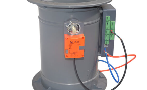
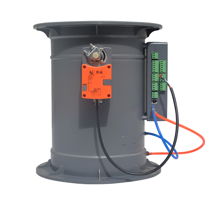
At its most fundamental engineering level, a VAV air flow damper is a precision-manufactured motorized valve or rotating blade assembly designed to modulate the specific volume of air entering a designated zone or being extracted from an industrial process. In a Variable Air Volume (VAV) architecture, the VAV air flow damper acts as the physical gatekeeper and flow regulator that responds dynamically to real-time environmental data.
Unlike legacy Constant Air Volume (CAV) systems—which operate like a light switch (either 100% on or 100% off)—the VAV air flow damper operates like a dimmer switch. It is designed to modulate, meaning the blade can rotate to any position between fully open (0° degrees) and nearly closed (90° degrees) to throttle the airflow. The primary purpose of a VAV air flow damper is to facilitate “demand-controlled ventilation.” By aligning the mechanical output of the ventilation system with the actual thermal or chemical load—a strategy strictly enforced by ASHRAE’s technical standards—industrial operators can eliminate the massive energy waste associated with over-ventilating unoccupied or low-demand spaces.
Critical Role of VAV Dampers in a Complete HVAC System
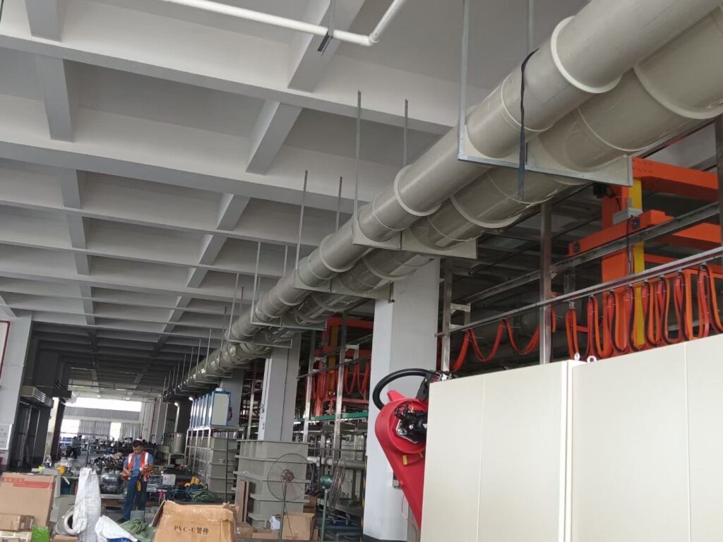
In a complete, integrated HVAC infrastructure, the VAV air flow damper serves as the vital link between the centralized Air Handling Unit (AHU) and the localized terminal zone. Its role is inherently systemic. When dozens or even hundreds of VAV air flow damper units across a sprawling facility adjust their positions to meet local temperature setpoints, they collectively influence the total static pressure within the main ductwork.
Advanced pressure sensors within the ducting detect these micro-fluctuations, signaling the central supply fan to ramp its RPM up or down via a Variable Frequency Drive (VFD). This creates a highly efficient “feedback loop.” Without a high-performance VAV air flow damper at the end of each branch, the entire system loses its ability to vary volume, forcing the central fans to run at maximum capacity regardless of actual demand. For global enterprises, the reliability of the VAV air flow damper directly correlates to lower operational expenditures (OPEX) and extended equipment lifecycles.
Key Distinction: VAV Damper vs. VAV Box (Common Industry Confusion)
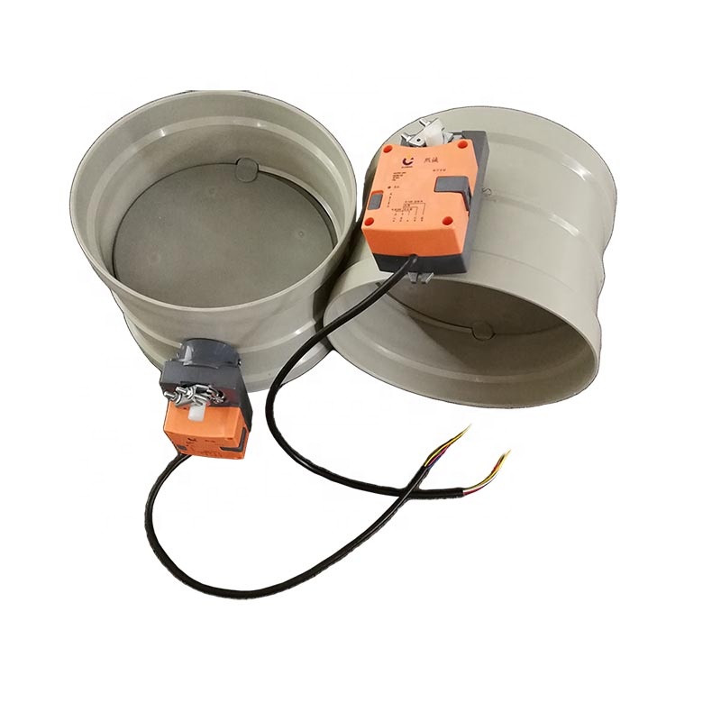
A frequent point of friction in global procurement and technical documentation is the blurred distinction between a VAV air flow damper and a “VAV box.” While these terms are often used interchangeably in casual site meetings, they represent different levels of mechanical assembly. A VAV box (also known as a terminal unit) is the entire exterior sheet-metal enclosure installed into the ductwork. It is a “system-in-a-box” that typically includes a controller, a flow sensor (pitot tube), and often a reheat coil for winter performance.
The VAV air flow damper, however, is the specific mechanical component inside that box. It is the actual rotating blade, shaft, and gasket assembly that performs the physical work of air restriction. If a facility manager reports a “stuck valve,” they are usually referring to a failure of the VAV air flow damper mechanism itself, not the electronics of the box. For high-durability industrial applications, selecting a robust VAV air flow damper—such as the Prolon PL-AV08—ensures the mechanical integrity of the entire terminal unit.
How Does a VAV Air Flow Damper Work?
Core Operating Principle of Variable Air Volume Dampers
The core operating principle of a VAV air flow damper is rooted in the physics of fluid dynamics and precise thermal load management. The fundamental strategy of a VAV-based system is to deliver conditioned air at a constant, optimized temperature (typically around 55°F or 13°C) while varying the Cubic Feet per Minute (CFM) to match the cooling or heating load.
The VAV air flow damper enables this by changing the effective cross-sectional area of the duct. As the damper blade rotates toward a closed position, it increases the air resistance (static pressure) in that branch, thereby reducing the volume of air that can pass through to the room diffusers. Most modern industrial dampers utilize “pressure-independent” control. This means the VAV air flow damper and its controller monitor the actual airflow speed, ensuring that even if pressure spikes elsewhere in the building, the local zone receives the exact volume of air required.
Step-by-Step Working Process in an HVAC System
To visualize the technical efficiency of the VAV air flow damper, one must observe its operational sequence:
- Sensing: A wall-mounted zone sensor or industrial thermostat detects that the ambient temperature has drifted 1-2 degrees away from the setpoint.
- Calculation: The localized VAV controller receives this data and calculates the required increase or decrease in CFM (Cubic Feet per Minute).
- Actuation: The controller sends a low-voltage signal to the motorized actuator, which physically rotates the VAV air flow damper blade to a precise angle.
- Response: As the room reaches the desired temperature, the VAV air flow damper “trims” back toward its minimum position (usually 20-30% open to maintain air quality), signaling the central fan to slow down.
This continuous modulation prevents the “on-off” temperature swings typical of older systems and ensures that every watt of electricity consumed by the central fan is directly contributing to a needed thermal change.
The Role of Actuators and Controllers in VAV Damper Operation
A VAV air flow damper cannot function as an isolated piece of galvanized steel; it requires an electronic “brain” (the controller) and “muscle” (the actuator). The actuator is the high-torque motorized device that overcomes the air pressure within the duct to turn the damper shaft. In demanding industrial environments, these actuators must be rated for hundreds of thousands of cycles.
Modern control architectures, such as the Airzone VAV Solution, integrate advanced PID control logic. This allows a facility manager in London to monitor the real-time position of every VAV air flow damper in their New York facility via a cloud-based dashboard, ensuring that the entire global portfolio is operating at peak efficiency.
How VAV Dampers Adapt to Zone-Specific Temperature & Airflow Demands
The true industrial value of the VAV air flow damper lies in its granular adaptability. In a large manufacturing plant, you may have a “Clean Room” that requires massive airflow for filtration and a neighboring administrative office that requires very little. A single central air handler can serve both zones perfectly because each branch has its own VAV air flow damper.
According to research on VAV system performance, this zoned approach can reduce total building energy consumption by 30% to 50% compared to non-modulating systems.
Performance and Efficiency Comparison
| System Feature | Constant Air Volume (CAV) | VAV Air Flow Damper System | Global Industrial Benefit |
| Energy Consumption | 100% (Baseline) | 65% – 75% | Massive reduction in annual utility costs |
| Fan Power Usage | Constant / Maximum | Variable / Demand-Based | Significant reduction in mechanical motor wear |
| Zone Control | Uniform / Single Setpoint | Zoned / Individual Control | Targeted cooling for high-heat machinery |
| Airflow Stability | Constant Volume | Pressure-Independent Flow | Crucial for sensitive exhaust capture |
| Acoustic Performance | Constant Noise | Lower Noise at Part-Load | Improved working environment for personnel |