Industrial Air Damper Valve for Power Plant & Flue Gas Desulfurization (FGD) Systems: Complete Guide
Category : Blog
Power generation facilities face increasingly stringent emission regulations worldwide, with sulfur dioxide (SO₂) limits tightening across every major regulatory jurisdiction. At the heart of compliance lies the flue gas desulfurization system—a complex network of absorbers, scrubbers, and ductwork that removes SO₂ from exhaust gases before they reach the atmosphere. Controlling and directing these massive gas streams through the treatment process requires industrial air damper valves engineered to withstand extreme temperatures, corrosive chemical environments, and continuous high-pressure operation. A single underperforming damper can compromise an entire FGD train, forcing derating, unplanned shutdowns, or regulatory non-compliance with substantial financial penalties. Selecting the right industrial air damper valve for power plant and FGD applications demands a thorough understanding of damper types, material compatibility, sizing methodology, and lifecycle maintenance requirements. This guide provides power plant engineers, maintenance managers, and procurement professionals with a comprehensive resource covering damper fundamentals in FGD contexts, material and type selection for corrosive environments, and proven installation and maintenance practices that maximize equipment longevity and system reliability.
Understanding Industrial Air Damper Valves in Power Plant and FGD Contexts
What Are Industrial Air Damper Valves and Their Role in Power Plant Emission Control
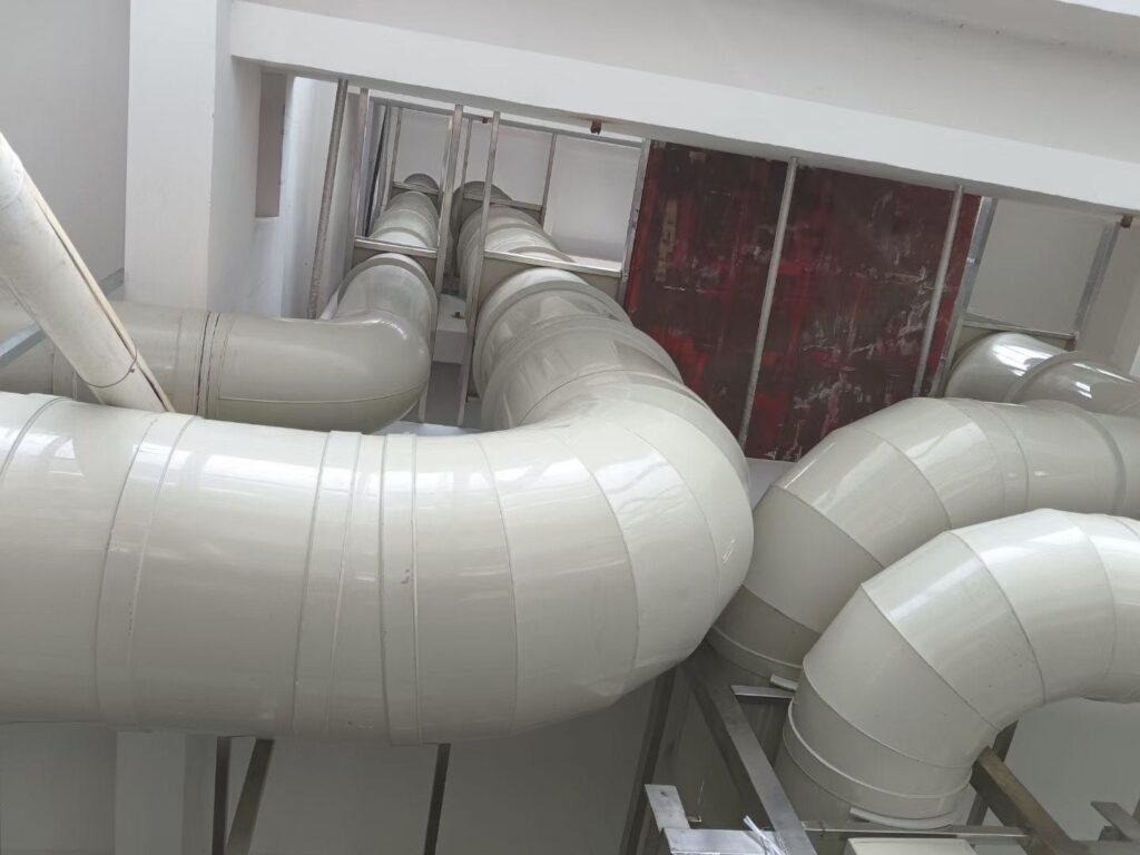
Industrial air damper valves are heavy-duty flow control devices installed within ductwork and gas handling systems to regulate, isolate, or redirect large-volume gas streams. In power plant emission control, these valves serve multiple critical functions: they direct flue gas from the boiler through selective catalytic reduction (SCR) systems for NOₓ removal, through electrostatic precipitators or baghouses for particulate control, and through FGD absorbers for SO₂ removal. Bypass dampers allow individual treatment stages to be isolated for maintenance without shutting down the entire generating unit. Isolation dampers seal off hazardous atmospheres during equipment inspections and turnaround activities. The scale of these industrial air damper valves is substantial—units in large coal-fired or gas-fired power plants commonly exceed 3 meters in diameter and must operate reliably across temperature ranges from ambient to 400°C, under differential pressures up to 5 kPa, and in gas streams laden with fly ash, acid mists, and dissolved chlorides. Failure to perform at any point in this chain results in emission exceedances, equipment damage, or safety incidents, making damper reliability a direct contributor to both environmental compliance and plant profitability.
How Flue Gas Desulfurization (FGD) Systems Utilize Air Dampers for Sulfur Dioxide Removal
Flue gas desulfurization systems use industrial air damper valves at multiple control points to manage the complex gas flow paths required for effective SO₂ removal. Raw flue gas enters the FGD ductwork through inlet dampers that regulate flow volume to match absorber capacity across varying boiler loads. Recirculation dampers redirect a portion of treated gas back through the absorber when inlet SO₂ concentrations exceed single-pass removal capacity. Bypass dampers provide the critical function of diverting flue gas around the FGD system during startup, upset conditions, or absorber maintenance, while maintaining continuous boiler operation. Outlet dampers control treated gas discharge to the stack and must maintain tight shutoff to prevent untreated gas from reaching the atmosphere during isolation events. The International Energy Agency (IEA) reports that wet limestone FGD systems—the dominant technology globally—achieve 95 to 99 percent SO₂ removal efficiency, but only when every damper in the gas path performs within specification. Even marginal leakage through a single bypass or isolation damper can reduce overall system removal efficiency below regulatory thresholds, making industrial air damper valve performance a non-negotiable element of FGD system design.
Key Performance Requirements for Air Dampers in Harsh Power Plant Environments
Industrial air damper valves in power plant and FGD service must meet demanding performance criteria that far exceed commercial HVAC damper requirements. Temperature resistance is paramount—dampers upstream of the FGD absorber handle flue gas at 120 to 180°C, while bypass dampers may encounter temperatures exceeding 350°C during emergency diversion events. Corrosion resistance is equally critical, as FGD environments expose damper components to saturated gas streams containing dissolved sulfuric acid, hydrochloric acid, chlorides, and abrasive fly ash particulates at pH levels between 2 and 6. Leakage performance must meet tight classifications—typically AMCA Class I or EN 1751 Class A—to ensure effective gas isolation and emission control. Structural integrity under continuous pressure loading, thermal cycling, and vibration from adjacent equipment must be maintained for service lives exceeding 15 years with appropriate maintenance. Actuation reliability is essential, as dampers must respond to control signals within seconds during load changes or emergency events. The U.S. Environmental Protection Agency (EPA) and equivalent regulatory bodies worldwide require continuous emissions monitoring that validates damper performance indirectly through stack emission data, making any damper-induced system deficiency immediately visible to regulators.
Types and Selection of Air Damper Valves for FGD Systems
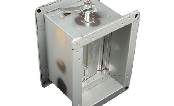
Common Types of Industrial Air Dampers: Butterfly, Louver, and Guillotine Valves for FGD Applications
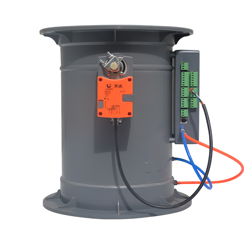
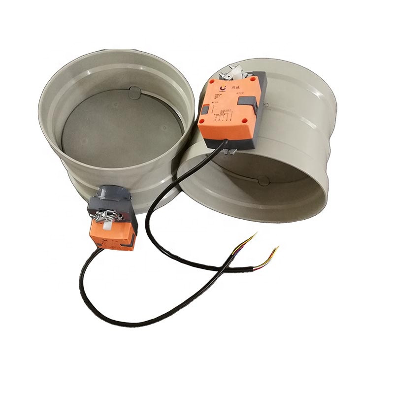
Three primary damper types dominate industrial air damper valve applications in power plant FGD systems. Butterfly dampers feature a circular disc rotating on a central shaft within a round or rectangular frame, offering compact installation, fast actuation, and good flow control characteristics for ducts up to 2.5 meters in diameter. Louver dampers consist of multiple parallel blades rotating in unison, providing larger flow area coverage and lower pressure drop across the blade array, making them preferred for high-volume flue gas ducts exceeding 3 meters in width. Guillotine dampers use a single solid plate that slides vertically or horizontally into the gas stream, delivering the tightest possible isolation seal with zero blade-through-duct leakage, and are the standard choice for critical isolation applications such as absorber inlet and bypass damper service. Each industrial air damper valve type presents distinct trade-offs: butterfly dampers offer simplicity and cost efficiency but higher leakage at large sizes; louver dampers handle large cross-sections but require more complex linkage systems; guillotine dampers provide superior sealing but demand greater installation space and heavier structural support. Selection depends on duct geometry, required leakage class, operating temperature, and whether the primary function is flow modulation or tight isolation.
Material Selection for Corrosive FGD Environments: Comparing Metals, Alloys, and Plastic Dampers
Material compatibility with the FGD gas environment is the single most important factor determining industrial air damper valve service life. Standard carbon steel dampers corrode rapidly in wet FGD conditions and are unsuitable for any application downstream of the gas cooling section. Stainless steel grades 316L and 317LM offer improved chloride resistance and are commonly used for damper frames and shafts in moderately corrosive zones. For aggressive wet FGD environments where chloride concentrations exceed 10,000 ppm and pH drops below 3, high-performance alloys such as Hastelloy C-276 or Inconel 625 provide the necessary corrosion resistance for damper blades and critical sealing surfaces. Lined dampers—carbon steel shells with internal rubber, fluoropolymer, or glass flake linings—offer a cost-effective alternative where full alloy construction is not economically justified. Plastic and FRP (fiberglass-reinforced plastic) dampers serve niche applications in low-temperature, low-pressure exhaust ducts where metallic options are unnecessary. Seal materials demand equal attention: PTFE-based flexible seals outperform elastomeric gaskets in acid mist environments, maintaining sealing integrity across wider temperature and chemical exposure ranges. The National Association of Corrosion Engineers (NACE) provides material selection guidelines that should be referenced during any industrial air damper valve specification for FGD service.
Sizing and Specification Criteria for Optimal Air Damper Valve Performance in Power Plants
Proper sizing of industrial air damper valves ensures both adequate flow capacity and acceptable pressure drop across the operating range. Damper face velocity should be maintained between 15 and 25 m/s for most FGD duct applications—velocities below 15 m/s risk particulate settling and erosion on horizontal duct sections, while velocities above 25 m/s generate excessive pressure drop and noise. The damper frame and blade assembly must be structurally rated for the maximum differential pressure encountered during worst-case scenarios, including emergency bypass events where pressure differentials can spike to 3 to 5 times normal operating values. Actuator torque selection must account for both aerodynamic forces on the blade and friction forces from seals under operating temperature conditions, with a safety factor of 1.5 to 2.0 applied to calculated torque requirements. Leakage class specification should reference the applicable standard—AMCA 500-D or EN 1751—with the required class determined by the damper’s function in the emission control chain. Critical isolation dampers demand the tightest class, while modulating control dampers may accept higher leakage tolerances where some flow bypass is operationally acceptable. Documenting all sizing calculations, material selections, and performance requirements in a formal damper specification ensures consistent procurement quality and provides the baseline for commissioning verification.
Installation, Operation, and Maintenance of Air Damper Valves in FGD Systems
Step-by-Step Installation Guide for Air Dampers in Power Plant Ductwork and FGD Units
Correct installation of industrial air damper valves directly determines whether laboratory-rated performance translates to field performance. Begin by verifying that the duct opening dimensions match the damper frame within the manufacturer’s tolerance—typically plus or minus 3 mm—and that structural supports are adequate for the damper weight plus dynamic loading from gas flow and seismic events. Lift and position the damper using designated lifting points only, never lifting by the actuator shaft or blade linkage. Secure the frame to the duct flange using high-temperature gasket material and torque all fasteners to specification in a cross-pattern sequence to ensure even compression. Connect the actuator and verify full stroke travel—blade must achieve complete open and closed positions without mechanical binding or over-travel. Install position feedback sensors and confirm signal accuracy against actual blade position at 0, 25, 50, 75, and 100 percent open. Conduct a pre-commissioning leakage test at design operating pressure, documenting results against the specified leakage class. For FGD applications, pay particular attention to drain provisions at the damper frame low point, as condensate accumulation in the frame cavity accelerates corrosion and compromises seal integrity. Complete the installation by applying corrosion-resistant coatings to all exposed fasteners and frame surfaces not protected by internal lining.
Operational Best Practices for Air Damper Valves in FGD Systems to Ensure Efficiency and Compliance
Operational discipline significantly extends industrial air damper valve service life and maintains emission compliance. Avoid holding dampers in partially open positions for extended periods unless specifically designed for modulating service, as intermediate positions expose seal edges to direct gas impingement and accelerated erosion. During boiler load changes, sequence damper movements to prevent sudden pressure surges that stress blade assemblies and actuator linkages. Monitor actuator torque trends over time—a gradual increase in closing torque indicates seal swelling, corrosion buildup, or bearing degradation, providing early warning before leakage becomes measurable. Integrate damper position and torque data into the plant’s distributed control system (DCS) to enable automated alarms when performance parameters deviate from baseline values. During FGD system startups, follow manufacturer-recommended warm-up sequences for hot bypass dampers to prevent thermal shock to blade and frame assemblies. The Electric Power Research Institute (EPRI) publishes operational guidance for FGD damper management that reflects decades of collective utility experience and should be incorporated into plant operating procedures. Consistent operational practices reduce unplanned maintenance events by 30 to 50 percent compared to reactive management approaches.
Maintenance Schedules, Inspection Checklists, and Troubleshooting for Longevity in FGD Applications
A structured maintenance program is essential for maximizing industrial air damper valve service life in corrosive FGD environments. Quarterly inspections should verify actuator operation, check for external corrosion on frames and linkages, and confirm seal condition through visual examination of accessible surfaces. Annual inspections during planned outages should include internal blade and seal inspection, measurement of seal wear against replacement criteria, lubrication of bearings and linkage pivot points, and recalibration of position feedback sensors. Every three to five years, conduct a full leakage test at operating pressure to quantify performance degradation and determine whether seal replacement or blade refurbishment is warranted. Common troubleshooting issues include increased leakage from seal wear or chemical attack, sluggish actuation from bearing corrosion or linkage binding, and uneven blade travel from thermal distortion. Documenting all inspection findings, maintenance actions, and test results in a damper-specific maintenance database enables trend analysis that predicts remaining useful life and optimizes replacement scheduling. For critical isolation dampers, maintain a spare seal kit and actuator on-site to minimize outage duration when repairs are needed. By treating industrial air damper valve maintenance as a proactive, data-driven program rather than a reactive repair activity, power plant operators sustain FGD system performance, extend equipment life, and maintain continuous regulatory compliance.
FGD Damper Application Matrix
| Damper Location | Recommended Type | Material | Leakage Class | Temperature Range |
|---|---|---|---|---|
| Absorber Inlet | Guillotine | Hastelloy C-276 / Lined CS | AMCA Class I / EN A | 120–180°C |
| Absorber Outlet | Butterfly or Louver | 317LM Stainless Steel | AMCA Class I / EN A | 50–80°C |
| Bypass Duct | Guillotine | Inconel 625 / 316L SS | AMCA Class I / EN A | 300–400°C |
| Recirculation | Butterfly | Rubber-Lined Carbon Steel | AMCA Class II / EN B | 40–70°C |
| Stack Inlet | Louver | 316L Stainless Steel | AMCA Class II / EN B | 50–90°C |
Sources: IEA FGD Technology Reports, EPA Emission Guidelines, NACE Material Selection Standards, EPRI FGD Operational Guidance.
For industrial air damper valves engineered for power plant and FGD applications—including high-temperature bypass dampers, corrosion-resistant isolation dampers, and custom-fabricated models for extreme service conditions—explore our complete product catalog.