The Complete Guide to Air Damper Types: Volume, Fire, Smoke, Backdraft & Motorized Dampers Explained

PP Air Valve

The Complete Guide to Air Damper Types: Volume, Fire, Smoke, Backdraft & Motorized Dampers Explained

Every HVAC system, ventilation network, and smoke control installation depends on air dampers to regulate, direct, and — when necessary — stop the movement of air through ductwork. Despite their critical role, air dampers are among the most frequently misunderstood components in building mechanical systems. Engineers and facility managers often specify dampers based on habit or price rather than a rigorous evaluation of the damper’s function, rating, and compatibility with the application. The consequences of a mismatched air damper range from inefficient airflow balancing and wasted fan energy to catastrophic fire spread through unprotected duct penetrations.

The world of air dampers encompasses a broad spectrum of types, each engineered for a specific purpose. Volume control dampers regulate airflow rate for system balancing. Fire dampers stop the passage of flame through fire-rated barriers. Smoke dampers resist the passage of smoke to maintain tenable evacuation conditions. Backdraft dampers prevent reverse airflow in exhaust and gravity systems. Motorized dampers enable automated, remote, and building-management-integrated control. Understanding the differences between these hvac damper types and functions — their construction, ratings, installation requirements, and maintenance needs — is essential for anyone responsible for specifying, installing, or maintaining ductwork systems. This guide provides a complete reference across all major air damper types, with practical selection criteria, code requirements, and lifecycle considerations drawn from leading industry standards.

Air Damper Types Including Volume

Understanding Air Damper Fundamentals: Function, Structure, and Classification

What Is an Air Damper and How Does It Control Airflow in HVAC Systems

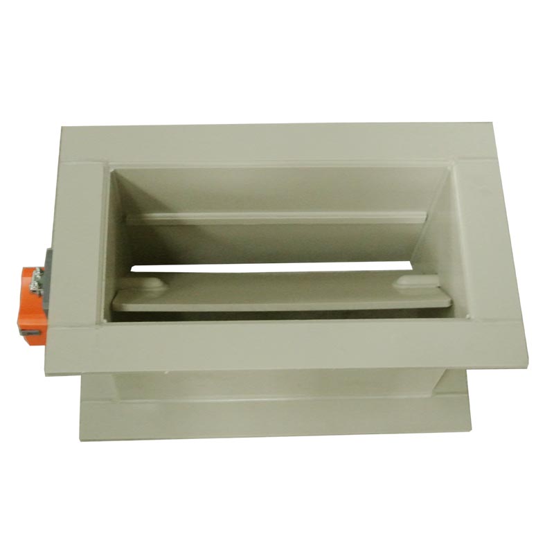
An air damper is a mechanical device installed inside or at the termination of a duct that controls the volume, direction, or passage of air by opening, closing, or modulating a set of blades (also called vanes or louvers) within a frame. When the blades are fully open, air passes through the duct with minimal restriction. When fully closed, the blades seal against the frame and each other to block airflow. At intermediate positions, the air damper modulates the flow rate, creating a variable resistance that the system fan must overcome.

In HVAC systems, air dampers serve multiple functions simultaneously. They balance airflow distribution across branch ducts, ensuring that each zone receives its designed supply volume. They modulate supply and return air to match real-time heating and cooling loads in variable air volume (VAV) systems. They isolate duct sections during maintenance or zone shutdown. And in life safety applications, they automatically close to prevent fire and smoke from spreading through the duct network to other building compartments. The automatic damper types used in modern buildings are sophisticated mechanical assemblies that must meet stringent performance, leakage, and durability standards defined by organizations such as UL (Underwriters Laboratories) and ASHRAE. Selecting the wrong type — or installing the right type incorrectly — can compromise the entire system’s performance and safety.

Key Components of an Air Damper: Blades, Frames, Linkages, and Actuators

Every air damper, regardless of type, consists of four fundamental components that work together to control airflow. The frame is the structural housing that mounts inside or on the duct, providing the sealing surface against which the blades close. Frames are typically constructed from galvanized steel, stainless steel, aluminum, or — for corrosive environments — polypropylene or other thermoplastics. The frame must be rigid enough to resist duct pressure without deflection, as any distortion creates gaps that leak air even when the damper is fully closed.

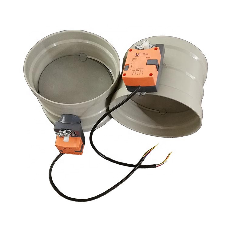
The blades are the movable elements that rotate within the frame to open or close the airflow path. Blade design varies by damper type: parallel blades rotate in the same direction and are used in volume damper vs balancing damper applications where low leakage is less critical; opposed blades rotate in opposite directions, creating a tighter seal and providing more linear flow control, making them preferred for modulating applications. Each blade is fitted with a seal — typically an elastomeric gasket or metal edge seal — that contacts the frame and adjacent blades when the damper is closed, minimizing leakage. The linkage connects all blades to a common operating shaft, ensuring synchronized rotation. Linkages may be internal (concealed within the frame) or external (mounted on the frame exterior), and they transmit the actuating force from the operator to the blades. The actuator provides the motive force to open and close the damper. Actuators may be manual (lever or hand quadrant), electric (motor-driven), pneumatic (cylinder-operated), or fusible-link-activated (for fire dampers). The choice of damper actuator types depends on the application: manual actuators for simple balancing, electric or pneumatic for automated control, and fusible links for life safety functions.

Air Damper Classification by Function: Control Dampers, Life Safety Dampers, and Combination Dampers

Air dampers are classified into three broad functional categories, each governed by different standards and code requirements. Control dampers — including volume control dampers and modulating dampers — are designed to regulate airflow under normal operating conditions. They are rated for leakage class per ASHRAE Standard 171 (formerly AMCA 500-D), with leakage classes ranging from Class I (lowest leakage, ≤3 CFM/ft² at 1″ w.g.) to Class IV (highest acceptable leakage for general HVAC). Control dampers are not rated for fire resistance and must not be used as substitutes for fire or smoke dampers.

Life safety dampers — including fire dampers, smoke dampers, and combination fire smoke dampers — are designed to protect building occupants by preventing the spread of fire and smoke through duct penetrations in fire-rated barriers. These dampers are tested and listed by UL under specific standards: UL 555 for fire dampers, UL 555S for smoke dampers, and UL 555C for combination fire smoke dampers. They must be installed in compliance with NFPA 80 (fire dampers) and NFPA 105 (smoke dampers). Combination dampers integrate both control and life safety functions in a single assembly — for example, a combination fire smoke damper that modulates airflow during normal operation and closes automatically upon detection of fire or smoke. The following table summarizes this classification:

CategoryFunctionKey StandardRating SystemTypical Application
Control DampersAirflow regulation and balancingASHRAE 171 / AMCA 500-DLeakage Class I–IVHVAC ductwork, VAV systems
Fire DampersBlock flame passage through fire barriersUL 555 / NFPA 80Fire rating (1.5 hr, 3 hr)Duct penetrations in fire walls
Smoke DampersBlock smoke passage through smoke barriersUL 555S / NFPA 105Leakage Class I at 250°FSmoke compartments, stairwells
Combination DampersFire + smoke protection in one unitUL 555CFire + smoke ratingHigh-rise buildings, hospitals

Air Damper Types Explained: Volume, Fire, Smoke, Backdraft, and Motorized Dampers

Volume Control Dampers: Regulating Airflow Rate and Balancing Duct Systems

Volume control dampers are the most common type of air damper in HVAC systems and are installed at branch takeoffs, main duct sections, and individual zone connections to regulate airflow distribution. The volume damper vs balancing damper distinction is often confused, but they serve different purposes: a volume control damper is a general-purpose damper used to adjust flow in any duct section, while a balancing damper is a precision instrument with a calibrated blade position indicator, designed specifically for system air balancing per ASHRAE Standard 111. Balancing dampers allow the commissioning engineer to set and lock each branch to its designed airflow volume, ensuring that the system delivers the correct amount of air to every zone.

Volume control dampers are available in parallel-blade and opposed-blade configurations. Parallel-blade dampers are simpler and less expensive but provide less linear flow control and higher leakage at partial closure. Opposed-blade dampers offer more uniform airflow distribution across the duct cross-section and better modulation characteristics, making them preferred for VAV applications where the damper must operate at intermediate positions for extended periods. Leakage performance is critical: ASHRAE 171 defines four leakage classes, with Class I representing the tightest seal (≤3 CFM/ft² at 1″ w.g.) and Class IV the loosest (≤30 CFM/ft²). For energy-efficient systems, Class I or II dampers are recommended to minimize the conditioned air wasted through closed or partially closed dampers.

Fire Dampers and Smoke Dampers: How They Protect Life Safety and Building Integrity

Fire dampers and smoke dampers are life safety devices that activate automatically to prevent the spread of fire and smoke through duct penetrations in fire-rated walls, floors, and partitions. The fire damper vs smoke damper difference is fundamental: a fire damper is designed to stop the passage of flame and is activated by a fusible link that melts at a rated temperature (typically 165°F / 74°C or 212°F / 100°C), slamming the damper blades closed. Fire dampers are tested per UL 555 and are rated for 1.5-hour or 3-hour fire endurance, matching the fire rating of the barrier they protect. They are required at every duct penetration through a fire-rated barrier per NFPA 80 and the International Building Code (IBC).

A smoke damper, by contrast, is designed to resist the passage of smoke — which kills more people in fires than flame itself. Smoke dampers are activated by smoke detection devices (photoelectric or ionization detectors) or by signals from the building fire alarm system, and they must close within approximately 75 seconds of activation. They are tested per UL 555S for leakage at elevated temperatures (250°F / 121°C) and must achieve Leakage Class I to prevent smoke migration through the closed damper. Smoke dampers are required at duct penetrations through smoke barriers — boundaries that divide a building into smoke compartments to maintain tenable evacuation conditions. The following table compares fire dampers and smoke dampers across key parameters:

ParameterFire DamperSmoke Damper
Primary FunctionBlock flameBlock smoke
Activation MethodFusible link (thermal)Smoke detector or fire alarm signal
Activation Temperature165°F or 212°F (link dependent)N/A (signal-activated)
Closing TimeImmediate upon link failure≤75 seconds upon signal
UL StandardUL 555UL 555S
Fire Endurance Rating1.5 hr or 3 hrN/A (smoke resistance only)
Leakage RequirementPer UL 555Class I at 250°F per UL 555S
Code ReferenceNFPA 80 / IBCNFPA 105 / IBC

Backdraft Dampers and Motorized Dampers: Preventing Reverse Airflow and Enabling Automated Control

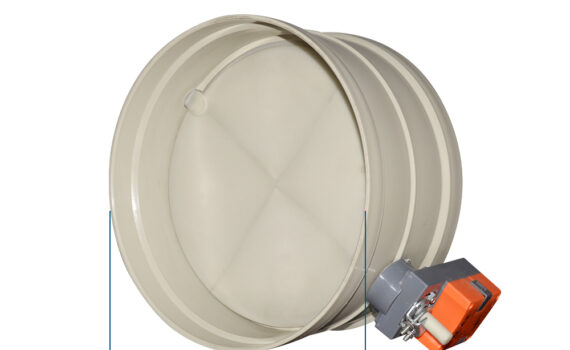
Backdraft dampers serve a unique and essential function: they prevent reverse airflow in duct systems where gravity, wind pressure, or system shutdown could cause air to flow backward through the duct. The backdraft damper how it works principle is simple: the blades are mounted on a horizontal or inclined axis and are held closed by gravity or a light spring. When airflow in the intended direction exceeds the blade’s cracking pressure (typically 0.05–0.15 in. w.g.), the blades open and allow air to pass. When the driving pressure ceases or reverses, the blades fall closed under their own weight, blocking backflow. Backdraft dampers are installed in exhaust duct terminations, gravity exhaust systems, kitchen hood exhausts, and toilet exhaust risers where reverse flow could introduce contaminated air back into the building.

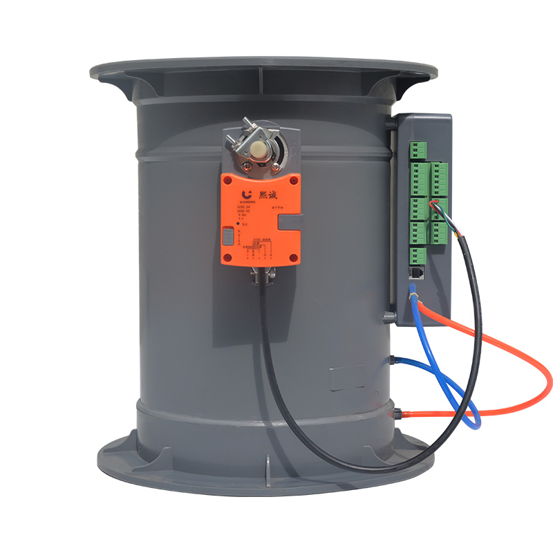
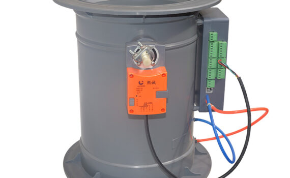
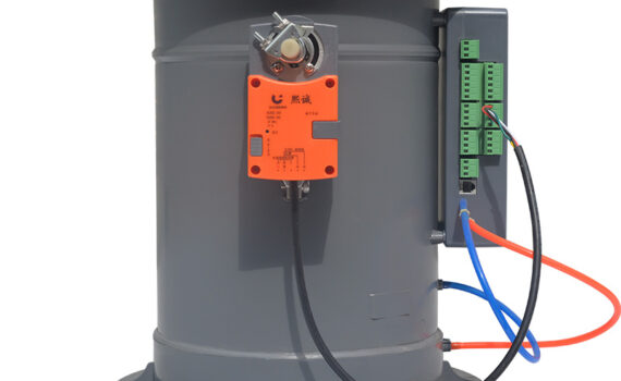
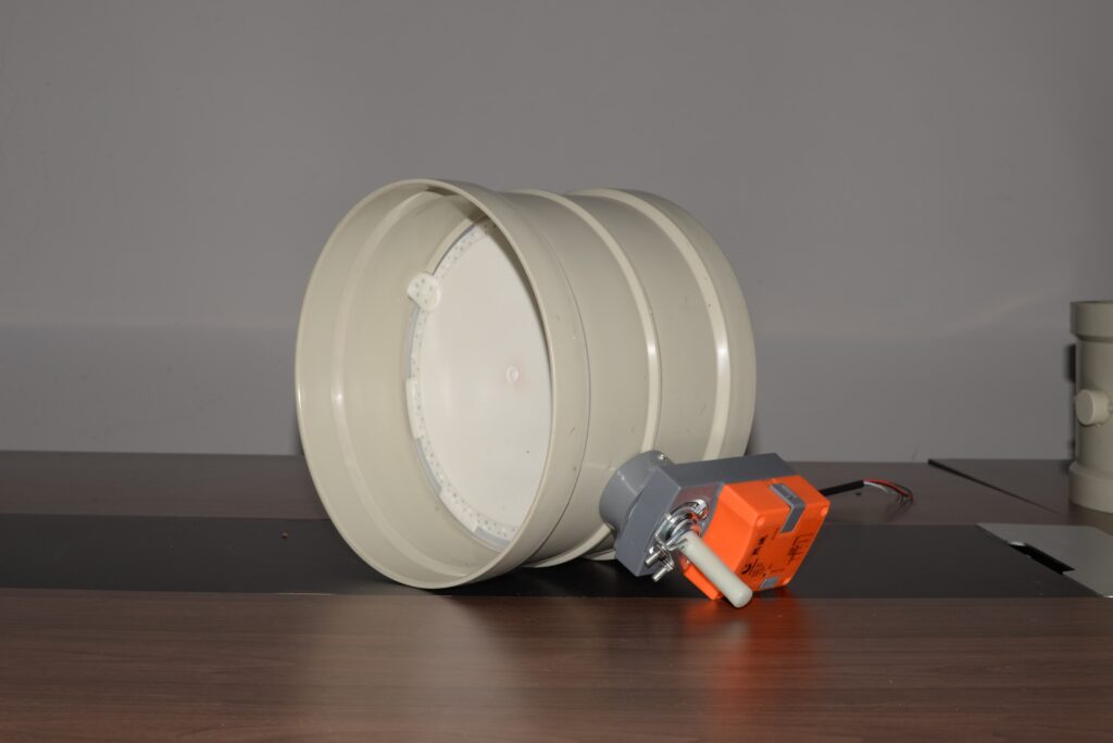
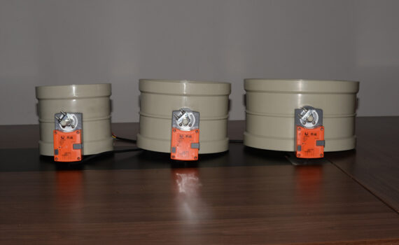
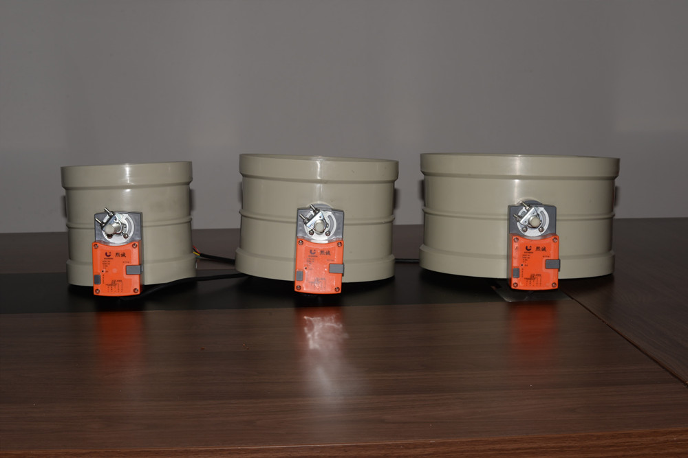
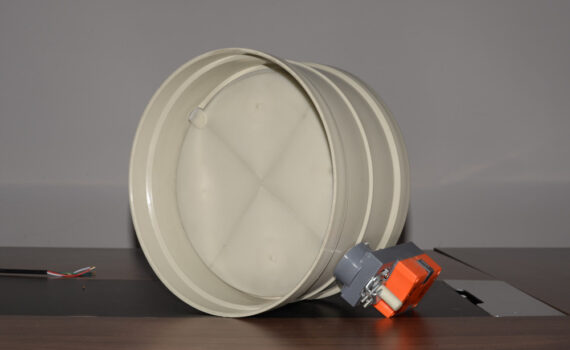
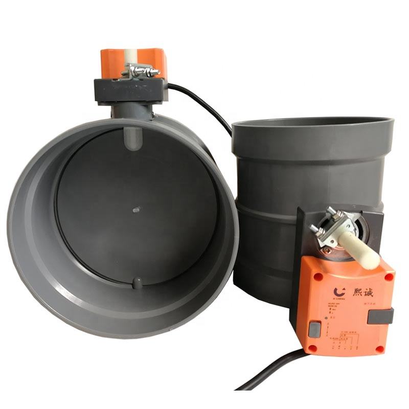
Motorized dampers — the motorized damper vs manual damper comparison is one of the most common specification decisions — use electric or pneumatic actuators to open, close, or modulate the blades in response to signals from a building automation system (BAS), thermostat, or fire alarm panel. Electric actuators are the most common, available in two-position (open/close), three-position, and modulating (proportional) configurations. Pneumatic actuators are used in facilities with existing compressed air infrastructure and offer fast response times. Motorized dampers are essential for VAV systems, economizer cycles (where outdoor air dampers modulate to provide free cooling), smoke management systems, and any application requiring remote or automated airflow control. Actuator selection depends on the required torque (which must exceed the damper’s operating torque at maximum system pressure), control signal type (on/off, 0–10V, 2–10V, or BACnet), and fail-safe position (open or closed upon power loss).

Factory exhaust air control system

Selecting, Installing, and Maintaining the Right Air Damper for Your Application

How to Choose the Right Air Damper Type: Media, Temperature, Pressure, and Code Requirements

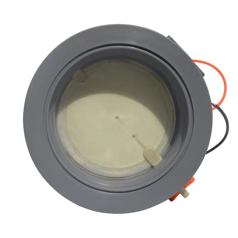
Selecting the correct air damper requires a systematic evaluation of five interdependent criteria. First, function determines the damper category: volume control, fire protection, smoke control, backdraft prevention, or automated modulation. Second, media compatibility dictates the body and blade material: galvanized steel for standard air, stainless steel for corrosive or high-humidity environments, and polypropylene or FRP for chemical exhaust systems. Third, temperature rating must exceed the maximum air temperature in the duct: standard dampers are rated to 250°F (121°C), high-temperature dampers to 500°F (260°C), and specialty dampers to 1000°F+ (538°C+). Fourth, pressure rating must accommodate the maximum system static pressure, including fan surge conditions.

Fifth, code requirements must be satisfied. UL rated damper types — including UL 555, UL 555S, and UL 555C listed dampers — are mandatory for life safety applications and must be installed exactly as tested and listed, including specific orientation, clearance, and mounting requirements. The following checklist summarizes the selection process:

Selection CriterionKey QuestionTypical Options
FunctionWhat is the damper’s primary purpose?Volume, fire, smoke, backdraft, motorized
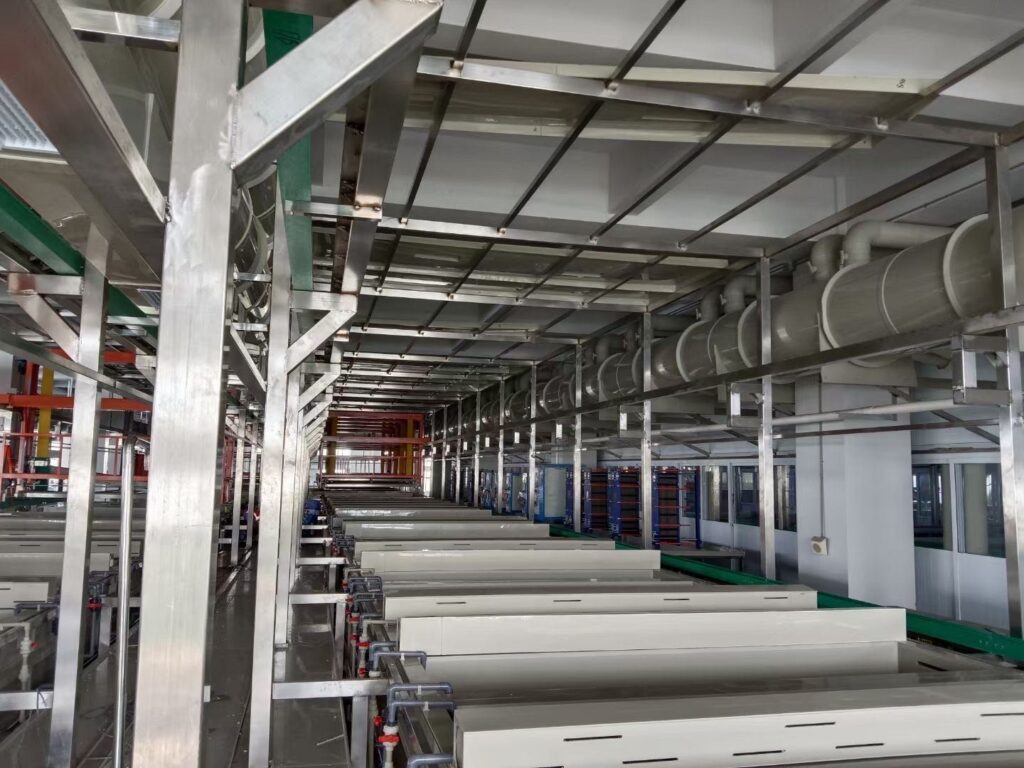
MediaWhat gas or air does the duct carry?Standard air, exhaust, chemical fumes
TemperatureWhat is the max air temperature?250°F, 500°F, 1000°F+
PressureWhat is the max duct static pressure?1–10 in. w.g. typical
Code / RatingIs a UL listing required?UL 555, UL 555S, UL 555C, or none
Actuator TypeManual, electric, pneumatic, or fusible?Per automation and safety requirements
Leakage ClassHow tight must the closed seal be?Class I–IV per ASHRAE 171

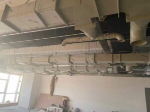
Air Damper Installation Best Practices: Placement, Mounting, and Sealing Guidelines

Proper installation is as important as proper selection — a UL rated damper type installed incorrectly loses its listing and fails to provide the intended protection. Fire dampers must be installed within the thickness of the fire-rated barrier they penetrate, oriented exactly as tested (horizontal or vertical), with the specified clearances between the damper frame and the barrier opening. The fusible link must be accessible for inspection and replacement. Smoke dampers must be installed with their actuator accessible for testing and must be connected to the building fire alarm system through approved relay or control panel interfaces.

For volume control and balancing dampers, installation best practices include mounting the damper at least three duct diameters downstream of any elbow, tee, or fan discharge to ensure uniform airflow across the blades. The damper must be supported independently of the duct to prevent differential movement from stressing the frame or linkage. All duct connections must be sealed with mastic or gasket to prevent leakage around the frame — a common source of energy waste that is invisible during operation but significant over the system’s life. For motorized dampers, the actuator must be mounted with adequate clearance for maintenance access, and wiring must be routed in conduit or plenum-rated cable per local electrical codes. The damper’s fail-safe position (open or closed upon power loss) must be specified during design and verified during commissioning.

Air Damper Maintenance, Inspection Schedules, and Common Failure Modes to Watch For

Air dampers require regular inspection and maintenance to remain functional, yet they are among the most neglected components in building mechanical systems — largely because they are hidden inside ductwork and out of sight. Life safety dampers are subject to mandatory inspection requirements: NFPA 80 and NFPA 105 require fire and smoke dampers to be inspected and tested one year after installation and then at intervals not exceeding four years (or six years for hospitals). Failure to comply voids the damper’s listing and exposes the building owner to liability.

Control dampers and motorized dampers should be inspected annually. The inspection protocol includes verifying that all blades open and close fully, checking linkage tightness and alignment, testing actuator operation through its full stroke, inspecting seals for wear or chemical degradation, and confirming that the damper’s leakage performance has not deteriorated. Common failure modes include seized blades (caused by corrosion, paint buildup, or debris accumulation), broken linkage pins (from fatigue or over-torque), failed actuators (motor burnout or pneumatic diaphragm rupture), degraded seals (from chemical attack or UV exposure), and corroded frames (particularly in outdoor or corrosive exhaust applications). For corrosive environments where metal dampers fail prematurely, polypropylene and FRP air damper alternatives offer dramatically extended service life due to their inherent chemical resistance. A disciplined inspection schedule, documented in a maintenance log, ensures that every air damper in the system continues to perform its intended function — whether that is balancing airflow, preventing fire spread, or enabling automated control — throughout the building’s operational life.

VAV air flow damper

variable air volume system control

What Is a VAV Air Flow Damper and How Does It Work in Your HVAC System?

In the increasingly complex landscape of global industrial facility management and specialized exhaust gas treatment, the efficiency of an HVAC (Heating, Ventilation, and Air Conditioning) system has transitioned from a secondary operational concern to a fundamental financial and environmental requirement. At the absolute heart of this efficiency sits a critical mechanical component: the VAV air flow damper. For procurement specialists, HVAC engineers, and facility owners operating on a global scale—from high-tech laboratories in Singapore to massive automotive manufacturing plants in Germany—understanding the granular nuances of how a VAV air flow damper operates is the essential first step toward achieving significant energy savings and superior indoor environmental quality.

As modern industrial buildings move toward “Smart Factory” models and more responsive infrastructures, the VAV air flow damper has become the primary mechanical tool for balancing the delicate trade-off between thermal comfort and the rising demand for a reduced carbon footprint. If your organization is currently navigating the transition to more sustainable air distribution, companies like ppairvalve.com provide the specialized hardware necessary to meet these rigorous international standards.

VAV air flow damper

What Is a VAV Air Flow Damper?

Core Definition & Primary Purpose of VAV Air Flow Dampers

At its most fundamental engineering level, a VAV air flow damper is a precision-manufactured motorized valve or rotating blade assembly designed to modulate the specific volume of air entering a designated zone or being extracted from an industrial process. In a Variable Air Volume (VAV) architecture, the VAV air flow damper acts as the physical gatekeeper and flow regulator that responds dynamically to real-time environmental data.

Unlike legacy Constant Air Volume (CAV) systems—which operate like a light switch (either 100% on or 100% off)—the VAV air flow damper operates like a dimmer switch. It is designed to modulate, meaning the blade can rotate to any position between fully open (0° degrees) and nearly closed (90° degrees) to throttle the airflow. The primary purpose of a VAV air flow damper is to facilitate “demand-controlled ventilation.” By aligning the mechanical output of the ventilation system with the actual thermal or chemical load—a strategy strictly enforced by ASHRAE’s technical standards—industrial operators can eliminate the massive energy waste associated with over-ventilating unoccupied or low-demand spaces.

Critical Role of VAV Dampers in a Complete HVAC System

In a complete, integrated HVAC infrastructure, the VAV air flow damper serves as the vital link between the centralized Air Handling Unit (AHU) and the localized terminal zone. Its role is inherently systemic. When dozens or even hundreds of VAV air flow damper units across a sprawling facility adjust their positions to meet local temperature setpoints, they collectively influence the total static pressure within the main ductwork.

Advanced pressure sensors within the ducting detect these micro-fluctuations, signaling the central supply fan to ramp its RPM up or down via a Variable Frequency Drive (VFD). This creates a highly efficient “feedback loop.” Without a high-performance VAV air flow damper at the end of each branch, the entire system loses its ability to vary volume, forcing the central fans to run at maximum capacity regardless of actual demand. For global enterprises, the reliability of the VAV air flow damper directly correlates to lower operational expenditures (OPEX) and extended equipment lifecycles.

Key Distinction: VAV Damper vs. VAV Box (Common Industry Confusion)

A frequent point of friction in global procurement and technical documentation is the blurred distinction between a VAV air flow damper and a “VAV box.” While these terms are often used interchangeably in casual site meetings, they represent different levels of mechanical assembly. A VAV box (also known as a terminal unit) is the entire exterior sheet-metal enclosure installed into the ductwork. It is a “system-in-a-box” that typically includes a controller, a flow sensor (pitot tube), and often a reheat coil for winter performance.

The VAV air flow damper, however, is the specific mechanical component inside that box. It is the actual rotating blade, shaft, and gasket assembly that performs the physical work of air restriction. If a facility manager reports a “stuck valve,” they are usually referring to a failure of the VAV air flow damper mechanism itself, not the electronics of the box. For high-durability industrial applications, selecting a robust VAV air flow damper—such as the Prolon PL-AV08—ensures the mechanical integrity of the entire terminal unit.

How Does a VAV Air Flow Damper Work?

Core Operating Principle of Variable Air Volume Dampers

The core operating principle of a VAV air flow damper is rooted in the physics of fluid dynamics and precise thermal load management. The fundamental strategy of a VAV-based system is to deliver conditioned air at a constant, optimized temperature (typically around 55°F or 13°C) while varying the Cubic Feet per Minute (CFM) to match the cooling or heating load.

The VAV air flow damper enables this by changing the effective cross-sectional area of the duct. As the damper blade rotates toward a closed position, it increases the air resistance (static pressure) in that branch, thereby reducing the volume of air that can pass through to the room diffusers. Most modern industrial dampers utilize “pressure-independent” control. This means the VAV air flow damper and its controller monitor the actual airflow speed, ensuring that even if pressure spikes elsewhere in the building, the local zone receives the exact volume of air required.

Plastic Air Damper Valve

Step-by-Step Working Process in an HVAC System

To visualize the technical efficiency of the VAV air flow damper, one must observe its operational sequence:

  1. Sensing: A wall-mounted zone sensor or industrial thermostat detects that the ambient temperature has drifted 1-2 degrees away from the setpoint.
  2. Calculation: The localized VAV controller receives this data and calculates the required increase or decrease in CFM (Cubic Feet per Minute).
  3. Actuation: The controller sends a low-voltage signal to the motorized actuator, which physically rotates the VAV air flow damper blade to a precise angle.
  4. Response: As the room reaches the desired temperature, the VAV air flow damper “trims” back toward its minimum position (usually 20-30% open to maintain air quality), signaling the central fan to slow down.

This continuous modulation prevents the “on-off” temperature swings typical of older systems and ensures that every watt of electricity consumed by the central fan is directly contributing to a needed thermal change.

The Role of Actuators and Controllers in VAV Damper Operation

A VAV air flow damper cannot function as an isolated piece of galvanized steel; it requires an electronic “brain” (the controller) and “muscle” (the actuator). The actuator is the high-torque motorized device that overcomes the air pressure within the duct to turn the damper shaft. In demanding industrial environments, these actuators must be rated for hundreds of thousands of cycles.

Modern control architectures, such as the Airzone VAV Solution, integrate advanced PID control logic. This allows a facility manager in London to monitor the real-time position of every VAV air flow damper in their New York facility via a cloud-based dashboard, ensuring that the entire global portfolio is operating at peak efficiency.

Factory exhaust air control system

How VAV Dampers Adapt to Zone-Specific Temperature & Airflow Demands

The true industrial value of the VAV air flow damper lies in its granular adaptability. In a large manufacturing plant, you may have a “Clean Room” that requires massive airflow for filtration and a neighboring administrative office that requires very little. A single central air handler can serve both zones perfectly because each branch has its own VAV air flow damper.

According to research on VAV system performance, this zoned approach can reduce total building energy consumption by 30% to 50% compared to non-modulating systems.

Performance and Efficiency Comparison

System FeatureConstant Air Volume (CAV)VAV Air Flow Damper SystemGlobal Industrial Benefit
Energy Consumption100% (Baseline)65% – 75%Massive reduction in annual utility costs
Fan Power UsageConstant / MaximumVariable / Demand-BasedSignificant reduction in mechanical motor wear
Zone ControlUniform / Single SetpointZoned / Individual ControlTargeted cooling for high-heat machinery
Airflow StabilityConstant VolumePressure-Independent FlowCrucial for sensitive exhaust capture
Acoustic PerformanceConstant NoiseLower Noise at Part-LoadImproved working environment for personnel


Industrial air damper valve installation in power plant FGD ductwork

Stop Using Stainless Steel: 5 Reasons to Choose PP Dampers for Acidic Fume Systems

PP Dampers deliver unmatched performance in harsh environments. Engineers and specifiers worldwide now prefer PP Dampers over stainless steel for acidic fume systems. The switch brings clear, proven advantages in corrosion protection, cost efficiency, safety, and long-term reliability.

By choosing PP Dampers, facilities can eliminate the hidden risks and expenses associated with metallic components. This comprehensive guide explains exactly why PP Dampers have become the preferred solution for handling aggressive acidic exhaust streams.

air flow control CAV damper -1

Superior Corrosion Resistance of PP Dampers

How PP Dampers Withstand Highly Acidic Environments

Polypropylene (PP) is a high-performance thermoplastic polymer that offers exceptional resistance to a broad spectrum of aggressive chemicals. These include organic acids, inorganic acids, and strong alkalis that are commonly present in industrial exhaust streams from chemical processing, metal finishing, and pharmaceutical operations.

In real fume handling systems, PP Dampers face constant exposure to highly corrosive condensate. This forms when hot, moisture-laden acidic air cools inside the ductwork, creating concentrated acidic solutions that can reach pH levels as low as 1 or 2.

The molecular structure of PP provides complete chemical inertness. There are simply no free ions in the polymer matrix that can react with attacking acids, which completely prevents any chemical degradation, swelling, cracking, or material weakening over time. Unlike stainless steel that depends only on thin surface coatings or passive oxide layers for protection, PP Dampers deliver uniform, homogeneous resistance throughout the entire thickness of every component.

Modern PP Dampers also incorporate advanced UV stabilizers and impact modifiers during manufacturing. These additives ensure the units maintain perfect dimensional stability and tight sealing performance even under repeated thermal cycling conditions typical in industrial scrubber and exhaust systems.

As a direct result, PP Dampers routinely achieve operational lifetimes measured in decades, while stainless steel alternatives typically require replacement after just a few years of service.

The Failure Modes of Stainless Steel in Acidic Fume Systems

The popular term “stainless” unfortunately creates a false sense of security among many engineers and project specifiers. In severe acidic service conditions, even premium grades such as 316L stainless steel suffer from predictable and progressively destructive failure mechanisms that can compromise entire ventilation systems.

Pitting corrosion and crevice corrosion are the most frequent attack vectors. These are dramatically accelerated by the presence of chlorides, fluorides, and sulfates that are routinely found in industrial acid exhaust streams. When acidic condensate settles on damper blades, shafts, or housings, it systematically breaks down the protective chromium oxide layer that gives stainless steel its reputation. Once this passive film is breached, the underlying iron matrix becomes fully exposed, triggering aggressive galvanic corrosion that etches deep, stress-concentrating pits into the metal structure. Even more dangerous is Stress Corrosion Cracking (SCC). In environments that combine chlorides with tensile stress — exactly the conditions experienced by operating damper blades and rotating shafts — austenitic stainless steels can fracture suddenly and catastrophically without any significant prior metal loss or visible warning signs. Documented field studies of boiler chimney liners made from SS 304 have repeatedly shown accelerated wall thinning caused by acidic flue gas condensation. Chemical analysis of the deposits confirmed highly aggressive environments with pH values down to 2, dominated by sulfate ions that progressively destroy the metal. These failure modes prove that even systems originally designed as “dry” gas handling inevitably develop condensation points where liquid acid pools form, systematically destroying metallic components regardless of the alloy grade selected. For deeper technical insight, explore these external resources: A review of stress corrosion cracking of austenitic stainless steels and Stainless Steel Corrosion Case Studies. PP Dampers completely eliminate every one of these failure risks through their inherent material properties.

Real-World Examples of PP Dampers Outlasting Metal Alternatives

PP Dampers consistently demonstrate superior longevity across diverse industrial sectors including chemical processing, pharmaceutical manufacturing, semiconductor production, and metal finishing plants around the world.

In hydrochloric acid handling facilities within the chemical industry, operational records show that stainless steel dampers typically need complete replacement or extensive shaft and blade refurbishment within only 12 to 18 months after commissioning. The primary causes are bearing seizure and progressive edge erosion caused by ongoing acidic condensate attack. In identical applications, fully welded PP Dampers have delivered continuous, trouble-free service for 8 to 10 years or longer, requiring nothing more than routine visual inspections.

One large metal finishing plant processing hexavalent chromium and nitric acid exhaust went through several material iterations. Coated carbon steel dampers failed completely within six months. Next, 316L stainless steel units lasted only two years before pitting and leakage forced another replacement.

The final switch to PP Dampers eliminated all corrosion-related degradation. At the same time, the much lighter PP Dampers reduced deadweight loading on existing ductwork supports by approximately 85 percent. This simplified structural engineering requirements and dramatically improved overall system reliability and safety.

These real-world performance differences have led to widespread industry recognition: for acidic fume environments, engineered PP Dampers have moved far beyond being a simple alternative and have established themselves as the definitive standard for predictable, long-term performance and operational peace of mind.

Cost Savings and Operational Efficiency with PP Dampers

Lower Material and Installation Costs Compared to Stainless Steel

The economic benefits of selecting PP Dampers begin the moment you issue a purchase order and continue through every stage of installation and commissioning. Stainless steel pricing is notoriously volatile and expensive due to the high content of nickel and molybdenum required in corrosion-resistant alloys such as 317L or duplex grades needed for truly aggressive acidic service.

In contrast, polypropylene benefits from stable global petrochemical supply chains and mature manufacturing infrastructure, delivering predictable and significantly lower base material costs for PP Dampers.

Beyond raw material savings, the dramatic weight difference creates major installation economies. A typical PP Damper weighs 50 to 70 percent less than a functionally identical stainless steel unit. This directly reduces freight expenses, simplifies logistics planning, and cuts transportation carbon emissions.

Installation teams can easily position and secure PP Dampers without needing cranes, hoists, or heavy lifting equipment. This eliminates specialized rigging costs and reduces total labor hours by up to 40 percent on many projects. The weight advantage also cascades to supporting infrastructure. Lighter PP Dampers allow the use of lighter-gauge ductwork supports, reduced structural steel quantities, and simpler foundation designs, generating substantial cost savings throughout the entire balance-of-plant construction phase.

Ventilation duct layout of electroplating plant

Reduced Downtime and Maintenance Expenses

Detailed operational expenditure analysis reveals the strongest long-term economic argument for adopting PP Dampers in acidic fume systems. Stainless steel dampers installed in corrosive service demand intensive, ongoing maintenance programs. Shafts require special acid-resistant lubricants, blades must be inspected frequently for early pitting, and housing seals often need replacement due to corrosion buildup on flange surfaces. Every maintenance intervention adds direct labor and material costs while exposing the facility to unplanned production interruptions. PP Dampers fundamentally break this expensive cycle. Their inherent material properties eliminate corrosion as a degradation mechanism entirely. The natural lubricity of polypropylene greatly reduces bearing and shaft seizure risks.

Additionally, the complete absence of rust scale formation prevents harmful particulate shedding that could otherwise damage downstream equipment such as fans, scrubber packing media, and sensitive control instruments. This built-in reliability translates into far fewer unplanned downtime events. For continuous manufacturing operations where each hour of lost production can cost tens of thousands of dollars, the predictable performance of PP Dampers delivers economic returns that quickly exceed any initial purchase price difference.

Energy Efficiency Gains from Lightweight PP Construction

Many hidden energy costs in fume handling systems accumulate steadily over the equipment’s operational lifetime, and the choice of damper material directly affects these ongoing expenses. Heavy stainless steel dampers require correspondingly large and power-intensive actuation systems — high-torque pneumatic or electric actuators that must overcome both friction and airstream pressure while moving heavy blades. The lightweight design of PP Dampers allows engineers to specify smaller, more energy-efficient actuators that still provide equal or better positioning accuracy and response speed. Furthermore, polypropylene surfaces are naturally smoother than mill-finished stainless steel. This reduces the friction factor and overall system pressure drop in airflow calculations.

Lower pressure drop enables centrifugal fans to operate at reduced speeds or against less resistance, resulting in proportionally lower electrical energy consumption while still delivering the required exhaust airflow volumes. Industry studies of ventilation and exhaust applications confirm that comprehensive use of polypropylene components — including PP Dampers, ductwork, and fittings — typically delivers average annual energy cost reductions of up to 20 percent compared with equivalent all-metallic systems. Over a typical 20-year facility lifespan, these savings represent a major contribution to both operational budgets and corporate sustainability goals.

Safety and Environmental Benefits of Choosing PP Dampers

Non-Corrosive and Non-Toxic Material Properties

Workplace safety and process integrity considerations make material selection a critical element of overall operational risk management. When stainless steel corrodes inside exhaust systems, the resulting metal oxides, rust particles, and corrosion byproducts do not simply vanish — they shed directly into the airstream. This can contaminate the very processes that exhaust systems are designed to protect. Cleanroom manufacturing, pharmaceutical production, and sensitive chemical bath applications cannot tolerate even microscopic metallic particulate contamination that affects product quality or introduces process variability. PP Dampers remove this contamination risk completely. The inert polypropylene surfaces never shed metallic particles, no matter how aggressive the airstream chemistry becomes. This ensures consistently pure exhaust streams and protects downstream process integrity at all times. Installation safety is another major differentiator. Stainless steel fabrication usually requires extensive hot-work permits, on-site welding, grinding, and the inherent fire hazards created by sparks in potentially explosive atmospheres. PP Dampers systems use only thermal welding or simple bolted flange connections. These methods completely eliminate ignition sources, allowing safe installation inside operating facilities or hazardous classified areas without production shutdowns.

Fire Resistance and Compliance with Safety Standards 

Earlier concerns about plastic materials in industrial ventilation focused mainly on fire performance. Today’s advanced PP Dampers fully address these issues through specially formulated fire-retardant (FR) polypropylene grades developed for safety-critical applications. While standard polypropylene can sustain combustion under continuous flame exposure, FR-treated variants include proprietary additives that inhibit ignition and dramatically slow flame spread rates once fire begins. These materials exhibit self-extinguishing behavior immediately after the ignition source is removed, effectively preventing fire propagation through connected ductwork systems. Leading PP Damper manufacturers subject their products to rigorous independent testing according to international standards such as UL 94, consistently achieving the highest V-0 classification. This rating confirms that combustion stops within ten seconds on vertically oriented samples. In the rare event of a fire inside exhaust ductwork, properly specified FR PP Dampers maintain sufficient structural integrity to support emergency system activation while blocking flame transmission to other areas of the facility. These units also comply fully with European EN 13501-1 classifications and major international building codes, providing certified fire protection that works hand-in-hand with their superior corrosion resistance.

Comparison Table

Comparison ParameterPP Dampers (Polypropylene)Stainless Steel (304/316L)Impact / Insight
Corrosion Resistance in AcidExcellent; chemically inert across entire pH rangeSusceptible to pitting, crevice corrosion, and SCCPP Dampers completely prevent acidic condensate damage
Specific Failure ModeUV degradation (only if unstabilized); minor thermal effects above 80°CStress Corrosion Cracking and pitting in chloridesStainless steel fails without warning; PP Dampers fail safely
Material Density~0.91 g/cm³ (extremely lightweight)~8.0 g/cm³ (very heavy)PP Dampers offer up to 8x weight reduction
Installation RequirementsSimple rigging; no hot work; minimal laborCranes, certified welders, extensive permitsPP Dampers cut installation time and costs dramatically
Maintenance FrequencyVery low; almost no bearing service neededHigh; frequent shaft seizure and blade pittingPP Dampers enable predictable scheduling and lower OPEX
Fire Safety RatingUL94 V-0 achievable with FR additivesInherently non-combustibleFR PP Dampers meet all global building and safety codes
Environmental FootprintLow carbon; fully recyclable at end of lifeHigh carbon; energy-intensive recyclingPP Dampers support sustainability and circular economy goals

Ready to upgrade your system?
Switch to PP Dampers today and enjoy decades of reliable, corrosion-free, cost-effective service in even the most aggressive acidic fume environments. Contact a qualified PP Damper supplier to begin your project evaluation and see the difference for yourself.


315MM Electric Air Damper Valve

Polypropylene electric damper working principle

Polypropylene Electric Damper is a mechanical device designed to regulate or control the flow of air in HVAC (Heating, Ventilation and Air Conditioning) systems. These dampers are primarily used to regulate air volume, pressure and temperature in ductwork. Polypropylene electric dampers are known for their durability, high performance and low maintenance requirements. In this article, we will discuss in detail how polypropylene electric dampers work.

Polypropylene Electric Damper

Polypropylene electric damper consists of frame, vanes and actuator. The valve body is made of polypropylene injection molding or PP board welding. Due to the strong corrosion resistance of polypropylene, polypropylene anti-corrosion dampers are usually used in highly polluted and highly corrosive chemical environments.

The working principle of polypropylene electric damper:

When the actuator opens, it rotates the vanes to the desired position, allowing air to flow through the ductwork. The position of the vanes determines the amount of air that is allowed through the damper. For example, if the blades are fully open, the maximum amount of air will pass through the damper, and if the blades are fully closed, no air will pass through the damper.

Polypropylene electric dampers can be controlled in a number of ways, including thermostats, timers, and sensors. The thermostat is used to regulate the temperature in the room, and when the desired temperature is reached, the thermostat signals the damper to close. A timer can be used to open and close the damper at specific times of the day, which is useful for energy saving purposes. Sensors can be used to detect if a room is occupied, and when the room is unoccupied, the damper can be closed to save energy.

electric rectangular duct damper -5

Polypropylene electric dampers are also designed to be maintenance-free, meaning they require no regular lubrication or adjustments. They are also designed to be self-cleaning, which helps reduce the risk of contamination in the air ducts.

In addition to durability and low maintenance requirements, polypropylene electric dampers are also distinguished by their high energy efficiency. By regulating the flow of air through ductwork, these dampers can help reduce energy consumption and lower utility bills. This is especially important in commercial buildings, where HVAC systems are a major source of energy consumption.

Polypropylene electric dampers are also designed for easy installation, which helps reduce installation costs and minimize downtime. They can be installed in new or existing ductwork and can be customized to meet a building’s specific needs.

In summary, Polypropylene Electric Dampers are an essential part of HVAC systems used to regulate the flow of air through ductwork. They are durable, energy efficient and low maintenance, making them ideal for commercial and industrial applications. By understanding how polypropylene electric dampers work, homeowners and facility managers can make informed decisions about their HVAC systems and ensure they are operating at peak efficiency. Contact us.


Electric Plastic duct Damper

Plastic duct damper advantages and applications

Plastic duct damper is a damper used in heating, ventilation, and air conditioning (HVAC) systems to regulate the flow of air through the ductwork. Dampers are typically installed within ductwork and can be used to control airflow in a single direction, or to block or divert airflow entirely.

There are many different types of plastic duct dampers on the market, each with their own unique features and benefits. Some key factors to consider when selecting a plastic duct damper include the size of the ductwork, the type of HVAC system being used, and the specific application of the damper.

Key Benefits of Plastic Duct Dampers

Durability and Corrosion Resistance
Unlike metal dampers, which can rust or corrode over time, plastic dampers are resistant to many types of chemical and environmental damage. This makes them ideal for harsh industrial environments as well as residential and commercial HVAC systems.

Easy to install
Unlike metal dampers, which are bulky and difficult to work with, plastic dampers are lightweight and easy to handle. This makes them ideal for use in tight spaces where manipulating larger components can be difficult.

Laboratory piping system installation
Types of Plastic Duct Dampers

Inline damper
These dampers are installed within ductwork and can be used to control unidirectional airflow. Inline dampers are typically manually operated, using a lever or dial that allows the user to adjust the damper position as desired.

Steering damper
These dampers are used to block or divert airflow within ductwork. Diverter dampers are commonly used in HVAC systems to control the flow of air between different areas or rooms and can be operated manually or through an automated control system.

 Electric Plastic duct Damper

In addition to in-line and split flow dampers, a variety of other plastic duct dampers are available including return flow dampers, volume control dampers. Backflow dampers are used to prevent backflow of air within the ductwork, while volume control dampers are used to regulate the flow of air within the system. Plastic air duct dampers can be made of flame-retardant PP/PVC, and the flame-retardant materials can

When selecting a plastic duct damper, it is important to consider the specific application of the damper. For example, if the damper will be used in an industrial setting, it may be important to choose a damper that is resistant to chemical and environmental damage. If the damper will be used in a residential or commercial HVAC system, it may be important to choose a damper that is easy to install and operate.

In addition to choosing the correct type of plastic duct damper, it is also important to ensure the damper is installed correctly. Improper installation can result in reduced efficiency and performance, and increased energy costs. It is important to work with a qualified HVAC contractor to ensure the damper is installed correctly and operating at peak performance.

In summary, plastic duct dampers are an important part of HVAC systems, allowing users to control the flow of air through the ductwork and improving the efficiency and performance of the system. There are many different types of plastic duct dampers on the market, each with their own unique features and benefits.


Email:xicheng023@outlook.com

Contact us