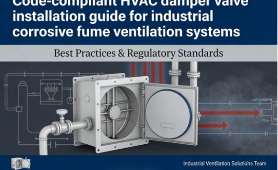
HVAC Damper Valve Installation: Step-by-Step Guide, Code Requirements & Best Practices
Category : Uncategorized
Proper HVAC damper valve installation is the foundation of safe, efficient, and code-compliant ventilation systems for residential, commercial, and industrial facilities.
Incorrect mounting leads to airflow imbalance, excessive energy use, premature equipment failure, and non-compliance with global safety standards.
This guide delivers a standardized, industry-approved workflow for HVAC damper valve installation, mandatory code requirements, and long-term performance best practices.
Step-by-Step HVAC Damper Valve Installation Process
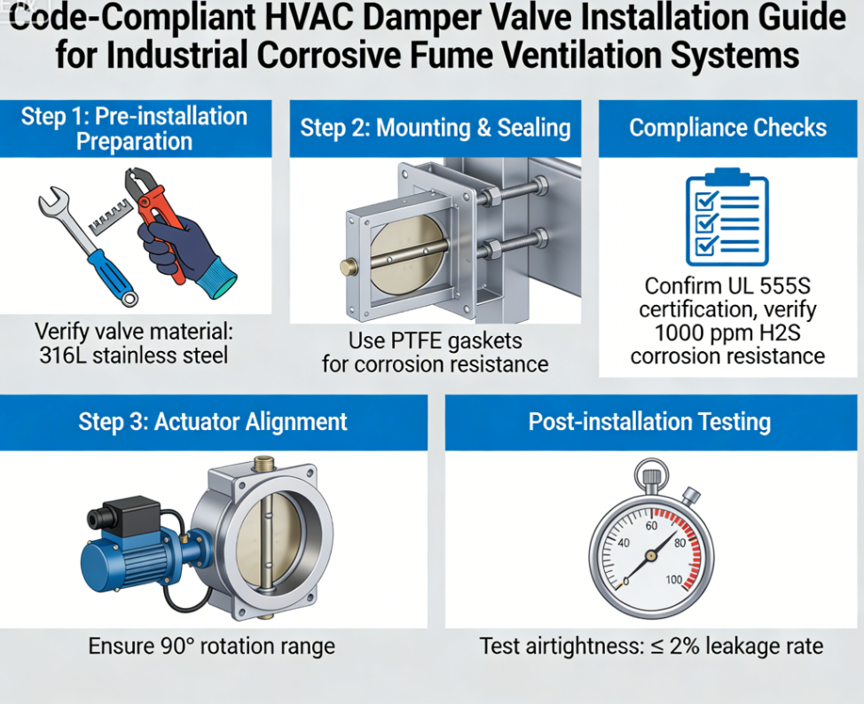
Pre-Installation Prep: Sizing, Placement & Tool Preparation
Correct pre-installation planning eliminates 60% of common HVAC damper valve installation errors, per the American Society of Heating, Refrigerating and Air-Conditioning Engineers (ASHRAE)’s HVAC Duct Design Standards .
Start by verifying the damper size matches your duct dimensions exactly, with no gaps that can cause air leaks or structural instability.
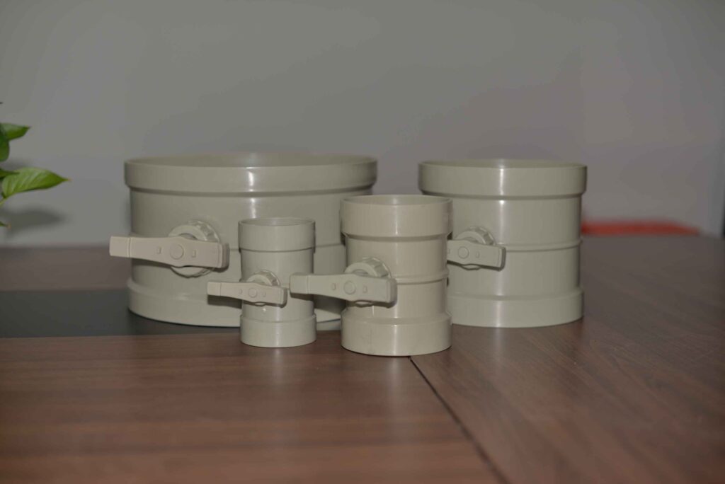
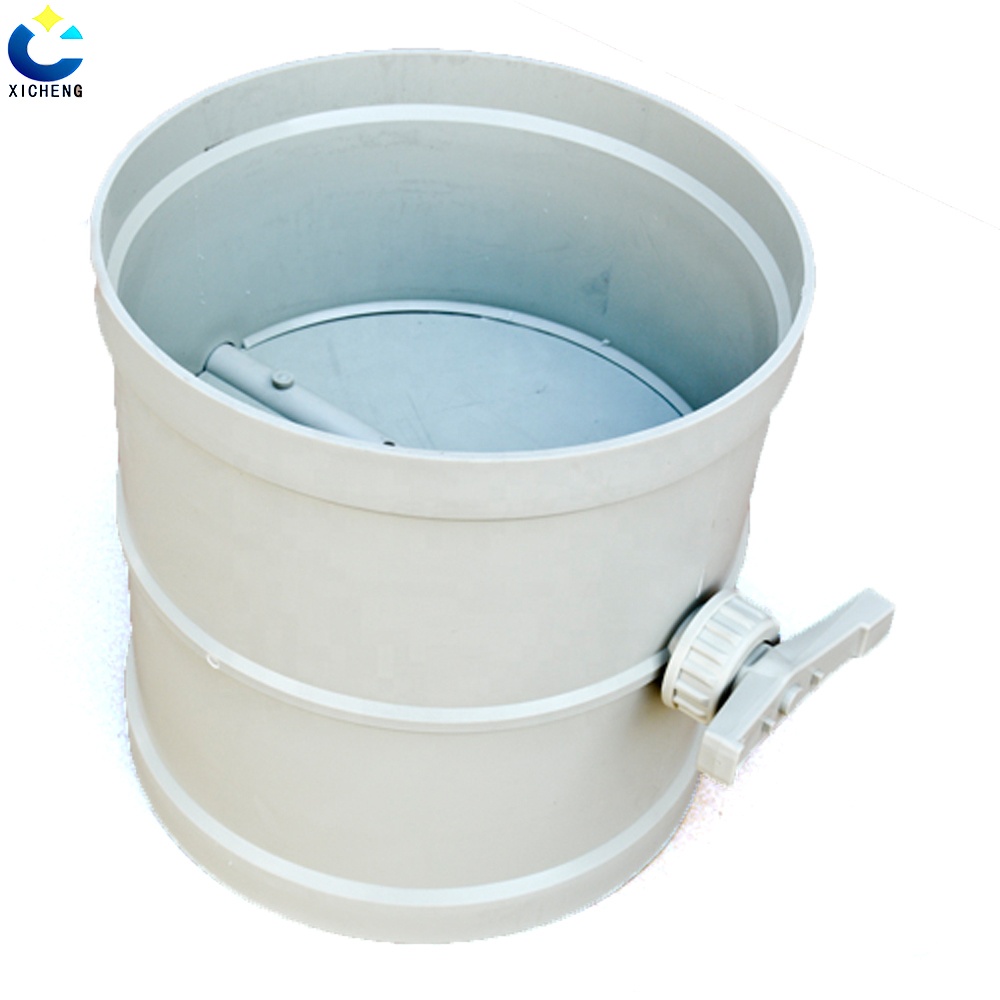
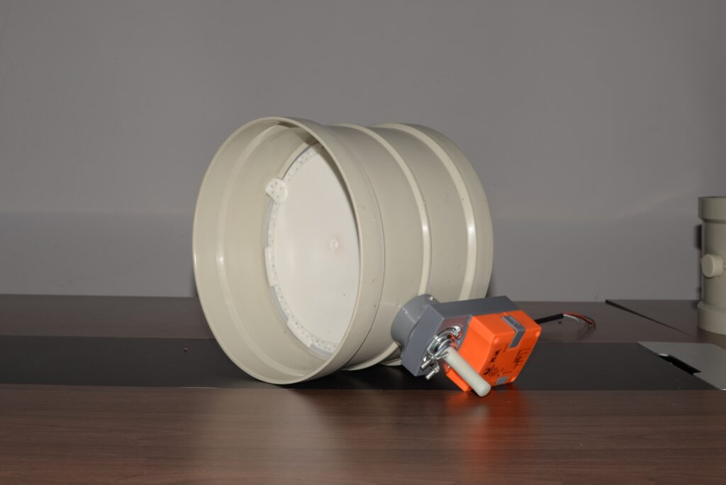
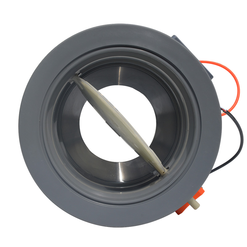
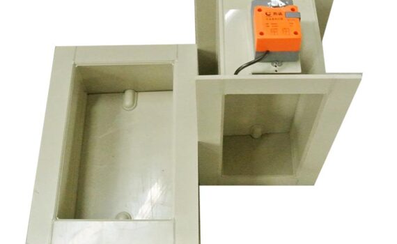
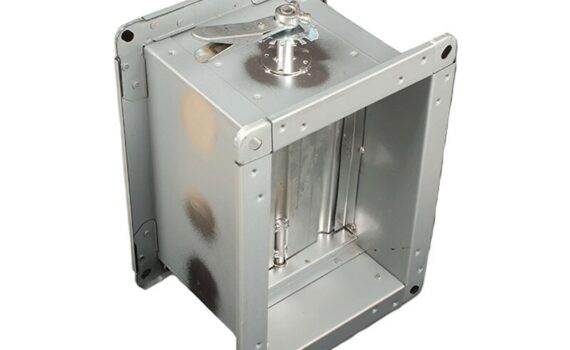
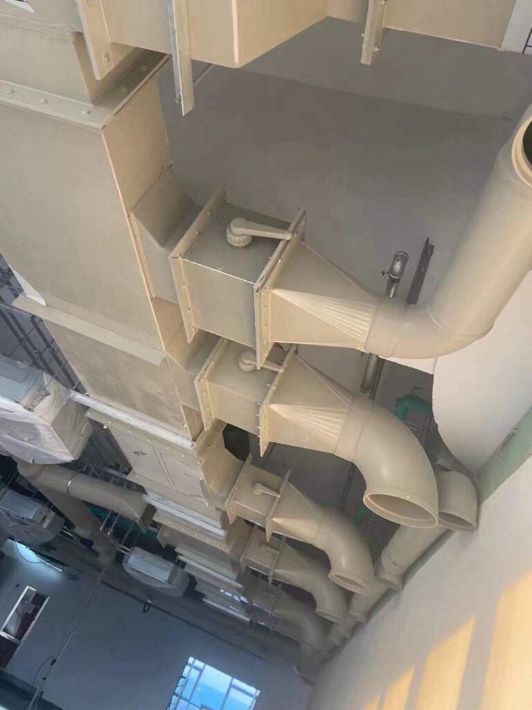
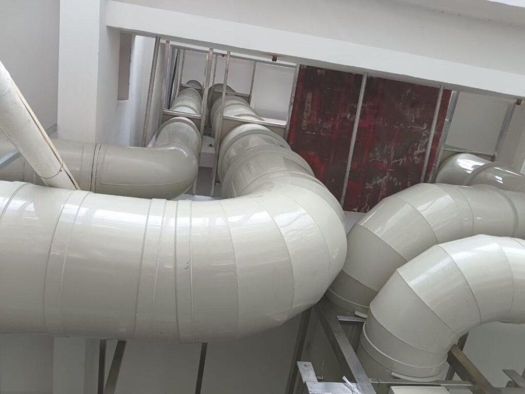
For corrosive industrial environments like chemical plants and laboratories, select chemically resistant PP/PVC dampers matched to your exhaust gas composition, with fully customized sizing and free drawing design available for non-standard ductwork .
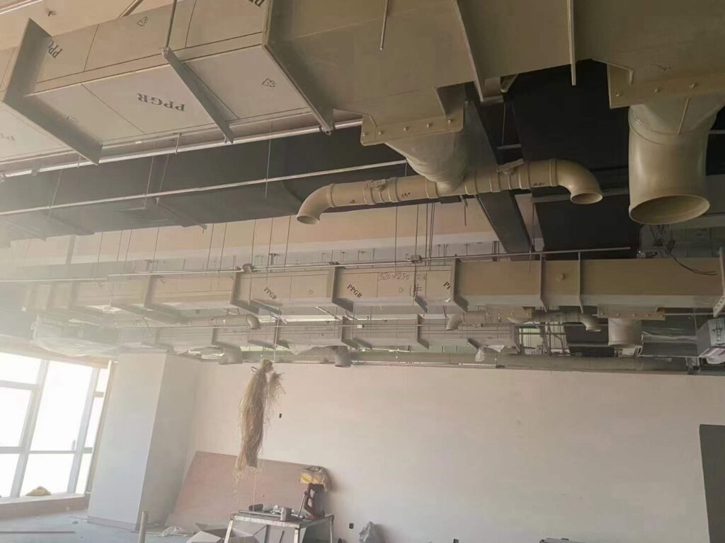
Confirm optimal placement: install dampers at least 1.5x the duct diameter away from elbows, fans, or transitions to avoid turbulent airflow disruption.
Gather required tools: drill, sheet metal screws, silicone sealant, anemometer, multimeter, and personal protective equipment for industrial installations.
Core Step-by-Step Damper Valve Mounting Process
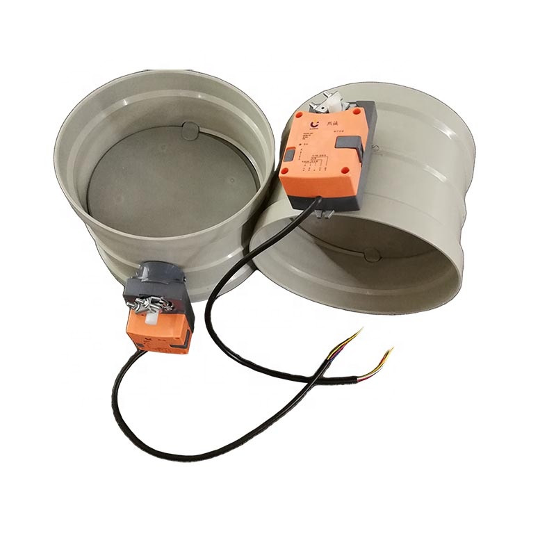
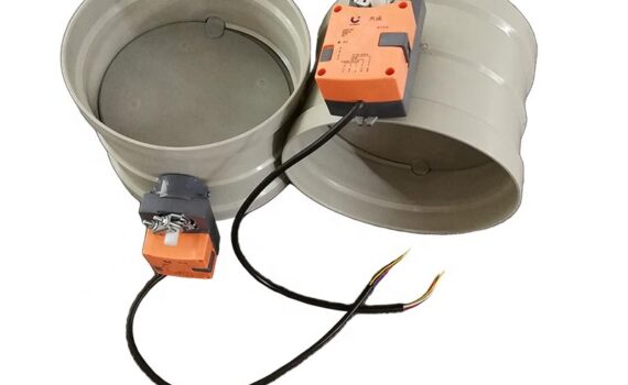
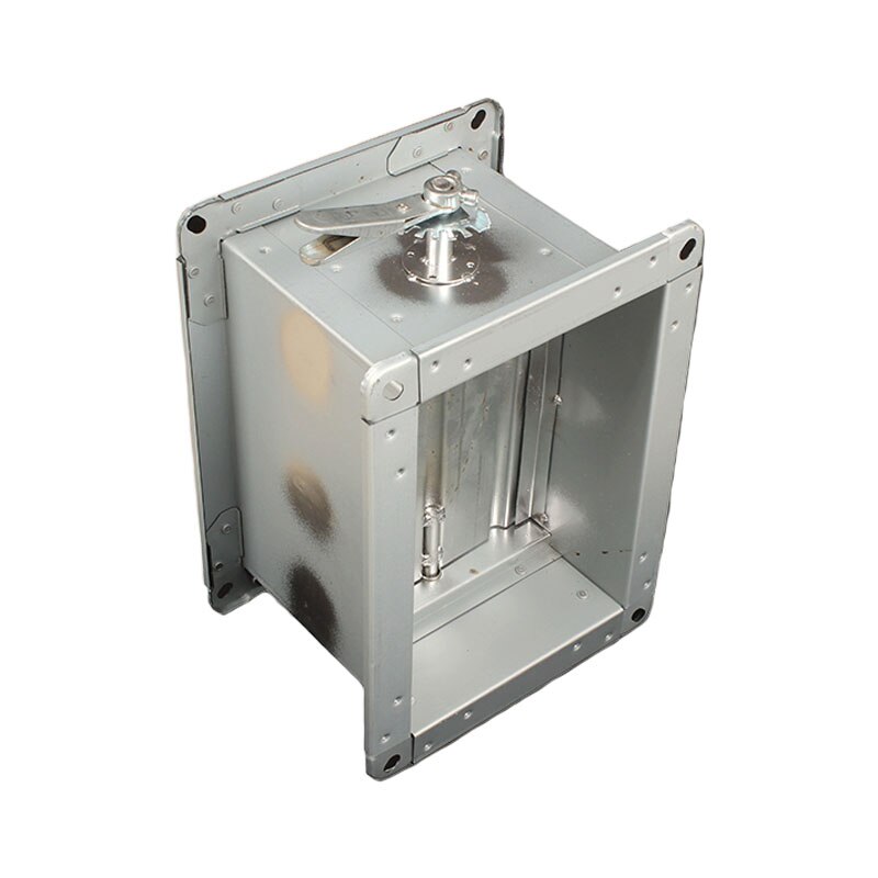
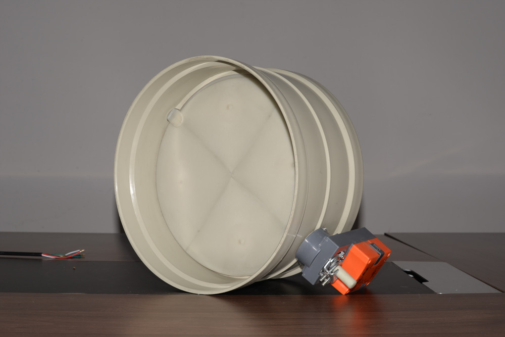
This standardized workflow applies to both manual and electric HVAC damper valve installation for round and rectangular ductwork.
First, mark the exact mounting location on the duct, ensuring the damper’s blade rotation direction aligns with the intended airflow path marked on the manufacturer label.
Cut the duct opening to match the damper’s flange dimensions, deburring edges to avoid damaging the damper seal during mounting.
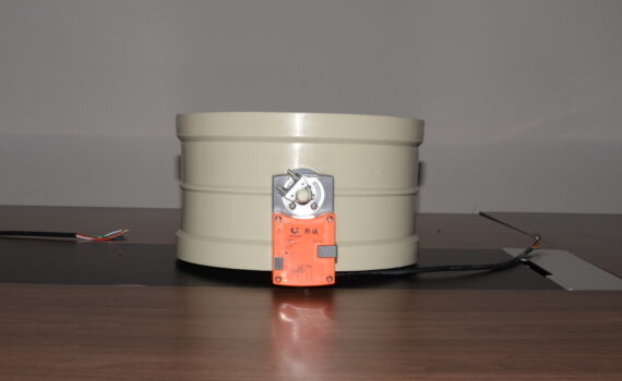
For manual dampers, align the damper body with the duct opening, secure the flange with sheet metal screws every 2-3 inches, and confirm the handle is fully accessible for adjustment.
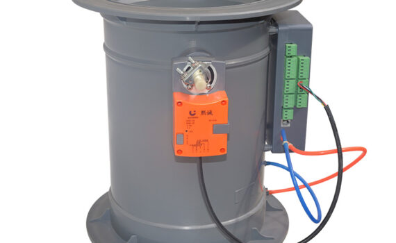
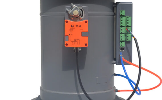
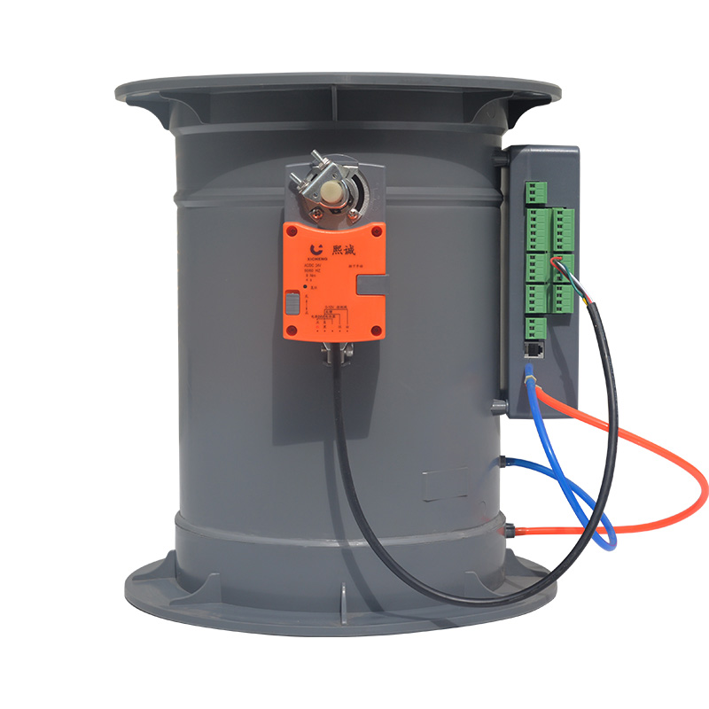
For electric dampers, complete mechanical mounting first, then wire the actuator to the zone control panel and thermostat, following local electrical code requirements.
Post-Installation Testing, Calibration & Function Check
No HVAC damper valve installation is complete without comprehensive testing to confirm functionality and safety.
First, perform a full open/close cycle test: for manual dampers, confirm smooth handle movement with no binding; for electric dampers, verify the actuator engages fully and responds correctly to thermostat commands.
Use an anemometer to measure airflow at fully open, 50% open, and fully closed positions, confirming the damper modulates airflow as intended.
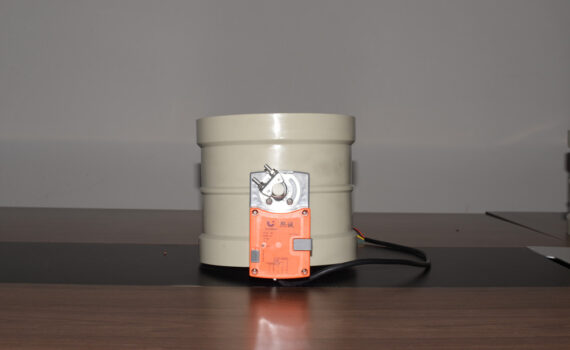
For VAV zone control dampers, calibrate the actuator to match the zone’s airflow requirements, ensuring precise control for variable exhaust or supply needs.
Finally, inspect all connection points for air leaks, and document all test results for code compliance and future maintenance.
Code Requirements for Damper Valve Installation
Fire & Smoke Damper Compliance with NFPA & UL Standards
Fire and smoke damper installation must follow strict national standards to ensure life safety in commercial and industrial buildings.
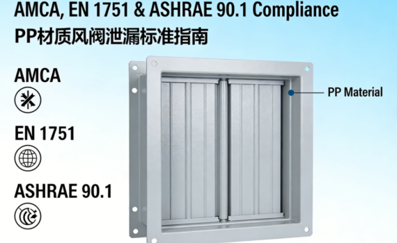
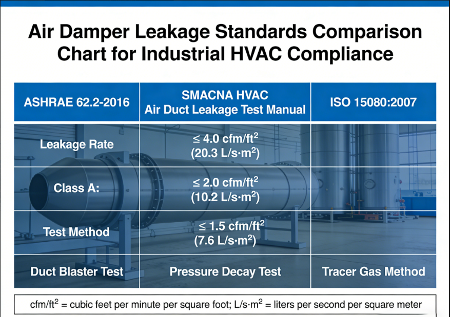
All fire dampers must meet UL 555 safety standards, and smoke dampers must comply with UL 555S, with factory-certified labels visible after installation.
Installation must fully align with NFPA 90A (Standard for the Installation of Air-Conditioning and Ventilating Systems) and NFPA 101 (Life Safety Code) , which mandate correct placement in fire-rated walls and floor assemblies, with no modifications to the factory-certified damper body allowed.
For industrial waste gas systems, additional requirements apply for dampers in explosion-proof or corrosive environments, with installation completed by qualified personnel only.
Local Building Code Requirements for Zone Control Dampers
Beyond national standards, your HVAC damper valve installation must comply with all local building code requirements.
Most local jurisdictions adopt the ICC International Mechanical Code (IMC), which sets minimum requirements for zone damper sizing, airflow control, and electrical wiring.
Some regions have additional energy efficiency requirements, mandating automatic shutoff dampers for unoccupied zones to reduce energy consumption.
For industrial facilities, local environmental and occupational safety codes may apply to exhaust system dampers, with mandatory documentation of installation compliance for regulatory inspections.
Mandatory Access & Inspection Requirements for Dampers
All code-compliant HVAC damper valve installation must include unobstructed access for future inspection, maintenance, and testing.
NFPA 90A mandates a minimum 18×18 inch access panel for all dampers, with no permanent obstructions blocking access to the damper body, actuator, or adjustment handles.
For dampers installed in ceiling plenums or hard-to-reach areas, access doors must be installed at the time of HVAC damper valve installation, not added after the fact.
Fire and smoke dampers require additional access to facilitate mandatory periodic testing, as required by NFPA standards every 1-4 years depending on the building type.

Industry Best Practices for Long-Term Damper Performance
Proper Sealing & Insulation for Damper Connection Points
Proper sealing is the most critical best practice to prevent air leaks and extend the lifespan of your HVAC damper valve installation.
Use UL-listed, fire-rated silicone sealant or mastic around all damper flange connections, avoiding cloth duct tape which degrades quickly in industrial or high-moisture environments.
For corrosive exhaust systems, use chemically resistant gaskets and sealants matched to your PP/PVC damper material, preventing leaks of hazardous fumes and protecting against acid and alkali corrosion.
For dampers installed in unconditioned spaces or outdoor ductwork, add closed-cell insulation around the damper body to prevent condensation, which can cause corrosion and premature failure.
Airflow Balancing Tips for Optimal Zone Performance
Even a perfect HVAC damper valve installation will underperform without proper airflow balancing across all zones.
Start by setting each damper to the fully open position, then measure the total system airflow to confirm it matches the design specifications.
Adjust each zone damper incrementally, using an anemometer to match airflow to the zone’s heating, cooling, or exhaust requirements.
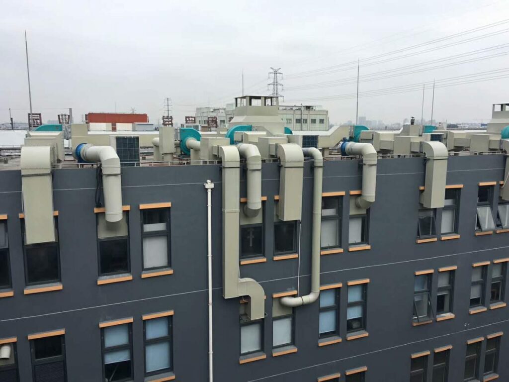
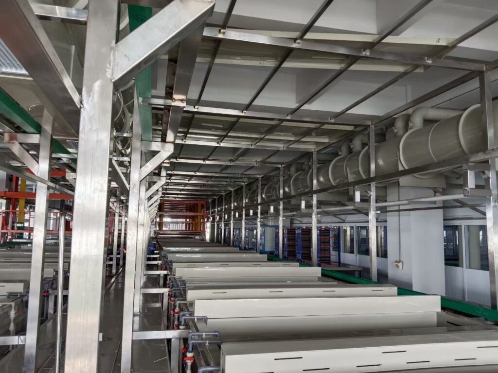
For industrial exhaust systems, balance dampers to ensure consistent capture velocity at all exhaust hoods, meeting Occupational Safety and Health Administration (OSHA) workplace air quality standards .
Document all final damper positions on your building’s mechanical drawings, to simplify future rebalancing and maintenance.
Routine Maintenance to Extend Damper Service Life
Following a consistent maintenance schedule will maximize the lifespan of your HVAC damper valve installation, with high-quality PP dampers lasting up to 50 years with proper care.
Perform quarterly visual inspections: check for corrosion, debris buildup on damper blades, loose hardware, and worn seals.
Lubricate manual damper pivot points and actuator gears annually with a silicone-based lubricant, avoiding oil-based products that attract dust and debris.
For industrial dampers in corrosive environments, perform monthly inspections to check for chemical damage, and replace worn seals promptly to prevent leaks.
Annually re-test damper operation and rebalance airflow, to maintain optimal performance and code compliance over time.
A code-compliant, professionally executed HVAC damper valve installation is the key to safe, efficient, and reliable ventilation performance.
By following this step-by-step guide, adhering to NFPA and local code requirements, and implementing industry best practices, you can minimize downtime, reduce energy costs, and extend the service life of your dampers.
For custom industrial PP/PVC dampers and full ventilation system design support, partner with an experienced manufacturer with 24/7 technical support and end-to-end installation guidance.