Category Archives: Blog

Aluminum Air Damper Valve

HVAC Damper Valve Types: Complete Guide to Choosing the Right One for Your System

Every HVAC system relies on a network of ductwork to deliver conditioned air where it is needed, but without properly selected damper valves controlling that airflow, even the most efficient equipment cannot deliver consistent comfort, energy savings, or code compliance. HVAC damper valves regulate air volume, isolate zones, protect against fire and smoke spread, and enable economizer cycles that reduce energy consumption—yet many system designers and facility managers treat damper selection as an afterthought. The consequences of poor selection are significant: uneven temperatures across zones, excessive energy waste from uncontrolled air leakage, failed fire safety inspections, and premature equipment replacement costs that far exceed the savings from choosing the cheapest damper available. With dozens of damper types, actuation methods, and material options on the market, understanding the core distinctions between damper categories and matching them to specific system requirements is essential. Whether you are designing a new commercial HVAC installation, retrofitting an existing building, or managing ongoing facility operations, this guide provides a clear framework for evaluating HVAC damper valve types, understanding their functional differences, and making selection decisions that optimize system performance, safety compliance, and total cost of ownership over the equipment lifecycle.

HVAC damper valve

Core Basics of HVAC Damper Valves

What Is an HVAC Damper Valve? Core Function Overview

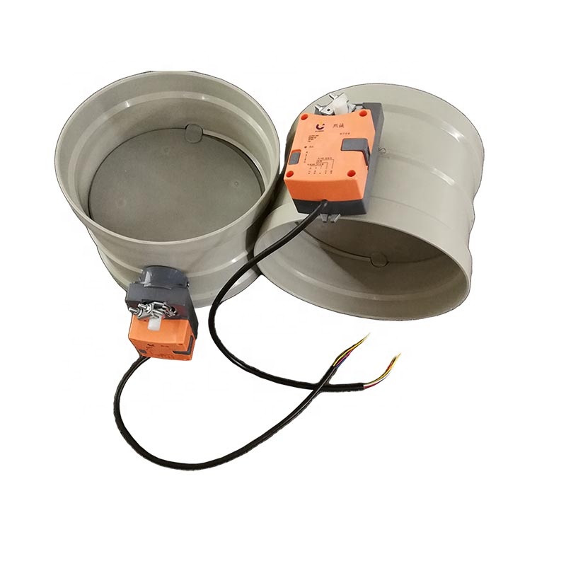
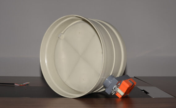
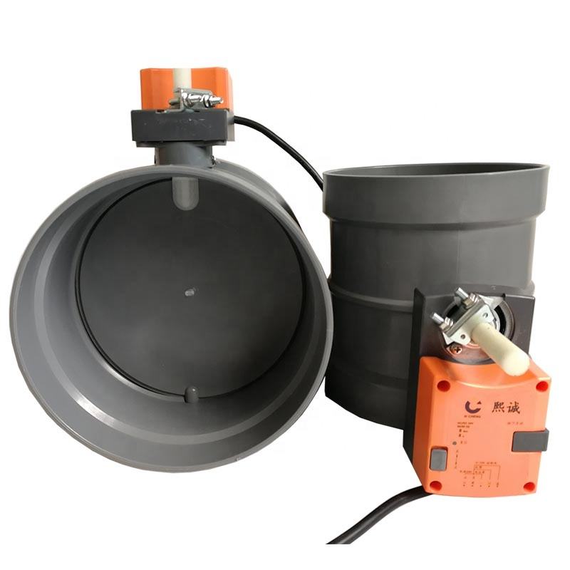
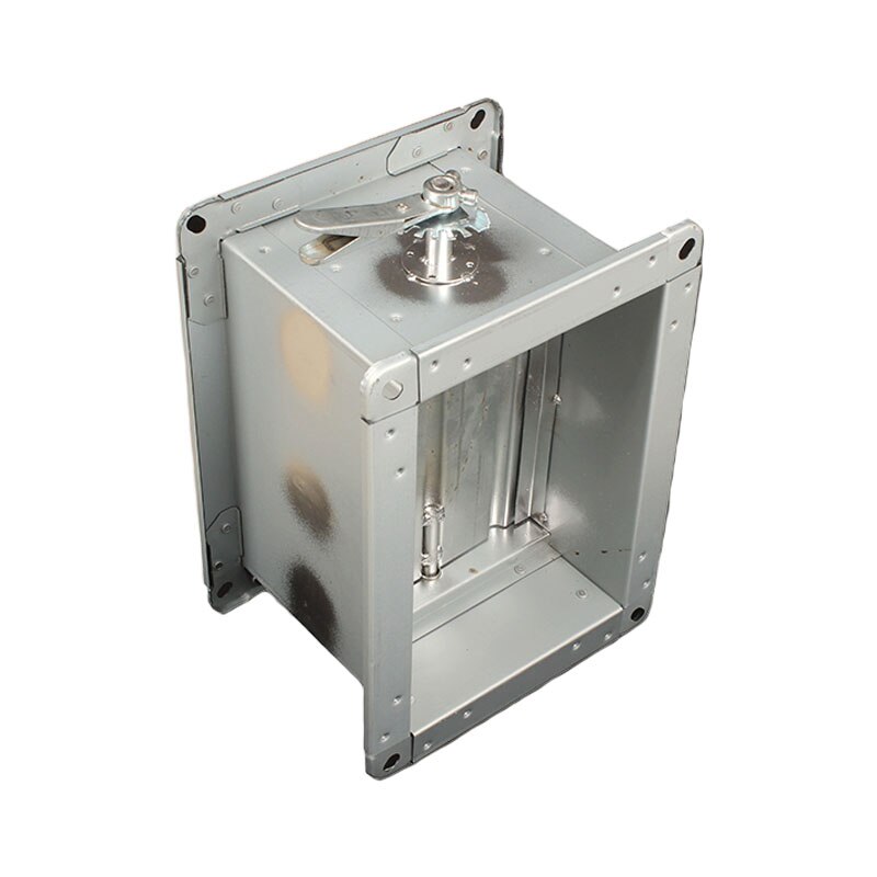
An HVAC damper valve is a mechanical device installed within ductwork that controls airflow by opening, closing, or modulating the passage area through which conditioned or exhaust air travels. At its most fundamental level, a damper consists of one or more blades mounted on a shaft within a frame, connected to an actuator that rotates or slides the blade(s) between open and closed positions. HVAC damper valves serve multiple system functions simultaneously: they regulate supply air volume to individual zones, balance airflow distribution across branch ducts, isolate sections of ductwork for maintenance or emergency purposes, and control outdoor air intake volumes in economizer and ventilation systems. The ASHRAE Handbook—HVAC Systems and Equipment classifies dampers by function, actuation method, and construction, recognizing that each application demands specific performance characteristics. A damper performing simple manual balancing in a residential branch duct has vastly different requirements than a motorized fire damper protecting a high-rise stairwell pressurization system. Understanding this functional diversity is the first step toward selecting the correct HVAC damper valve for any given application.

Why Proper Damper Selection Is Critical for HVAC Performance

Selecting the wrong HVAC damper valve creates cascading performance problems that compound over time. Undersized dampers generate excessive pressure drop, forcing fans to consume more energy while delivering less air to terminal zones. Oversized dampers lose modulation precision at low flow positions, creating control instability and occupant comfort complaints. Dampers with inadequate leakage ratings in economizer applications allow conditioned air to escape continuously, with ENERGY STAR research indicating that economizer damper leakage alone can increase cooling energy consumption by 10 to 25 percent in commercial buildings. In safety applications, the stakes are even higher—fire dampers that fail to close completely or smoke dampers with insufficient leakage ratings can allow flame and toxic gases to propagate through a building, violating fire codes and endangering occupants. The National Fire Protection Association (NFPA) mandates specific damper performance standards for life safety applications, and non-compliance can halt occupancy permits entirely. Proper HVAC damper valve selection is therefore not merely a technical optimization exercise—it is a direct determinant of energy efficiency, occupant safety, regulatory compliance, and long-term operational cost.

Key Factors That Impact Damper Valve Long-Term Reliability

Long-term reliability of HVAC damper valves depends on several interconnected factors that extend well beyond initial purchase price. Actuator quality is paramount—motorized actuators must deliver consistent torque over hundreds of thousands of cycles without drift or failure, and pneumatic actuators must maintain seal integrity under continuous pressure loading. Blade and shaft bearing design determines resistance to wear-induced play, which gradually increases leakage rates over the damper’s service life. Frame construction rigidity prevents warping under duct pressure loads and thermal cycling, maintaining blade-to-frame seal contact. Environmental exposure conditions—temperature extremes, humidity, chemical contaminants in the airstream, and vibration from adjacent equipment—all accelerate degradation of seals, bearings, and surface coatings. The U.S. Department of Energy emphasizes that HVAC component reliability directly correlates with maintenance accessibility, recommending that dampers be installed with sufficient clearance for inspection, lubrication, and actuator replacement without ductwork disassembly. Selecting HVAC damper valves from manufacturers with documented lifecycle testing data, rather than relying solely on catalog specifications, provides the most reliable predictor of long-term field performance.

PP Air Valve

Common Types of HVAC Damper Valves Explained

Zone Control Dampers: Precision Airflow Regulation for Zoned Systems

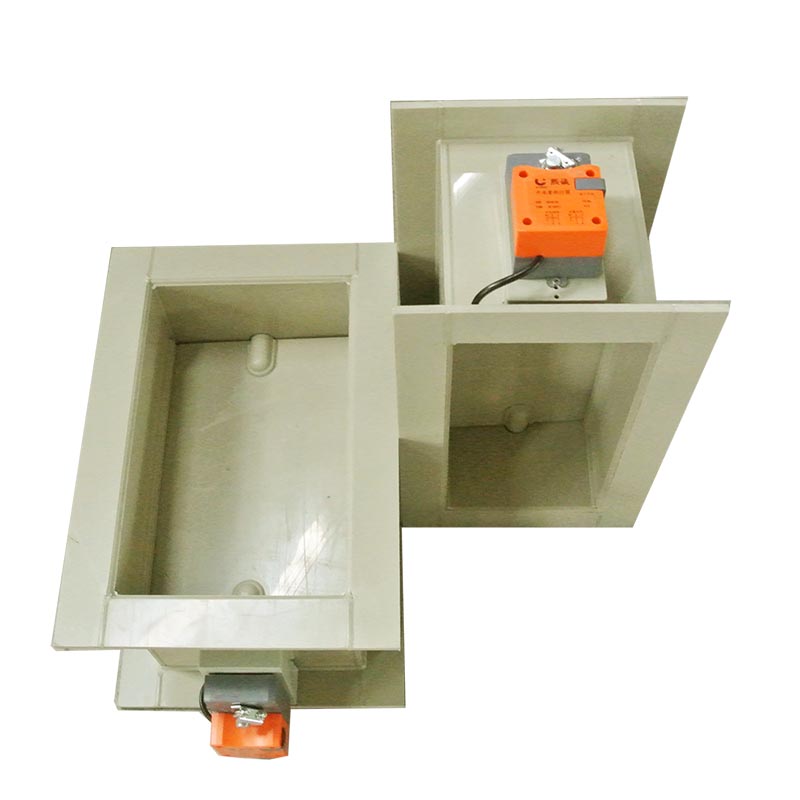
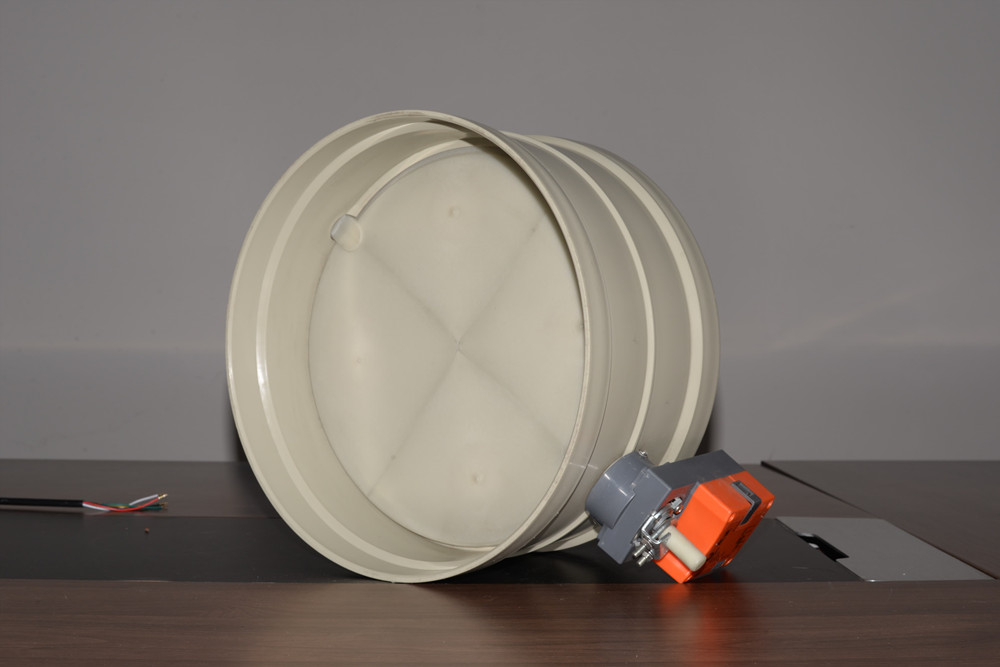
Zone control dampers are motorized HVAC damper valves installed at branch duct takeoffs to regulate airflow delivery to individual temperature zones within a building. Each damper receives commands from a zone controller that modulates blade position based on thermostat demand, allowing a single air handler to serve multiple zones with independent temperature setpoints. These dampers are typically round or rectangular to match branch duct geometry and use low-torque actuators optimized for frequent modulation rather than full open-close cycling. Effective zone control dampers feature low-leakage blade seals—typically rated to AMCA Class I or II—to prevent unconditioned air from migrating into satisfied zones when the damper is closed. The Building Efficiency Research Division estimates that properly implemented zone control with quality HVAC damper valves can reduce HVAC energy consumption by 20 to 30 percent compared to single-zone systems, while simultaneously improving occupant comfort by eliminating hot and cold spots. For multi-zone commercial buildings, zone control dampers represent one of the highest-return investments in the entire HVAC system.

Fire & Smoke Dampers: Safety-Critical Solutions for Code Compliance

Fire dampers and smoke dampers are specialized HVAC damper valves designed to maintain the fire-resistance rating of walls, floors, and barriers where ductwork penetrates fire-rated assemblies. Fire dampers contain fusible links that melt at a predetermined temperature—typically 74°C or 165°C—triggering spring-loaded blade closure that seals the duct opening against flame and hot gas passage. Smoke dampers are actuated by smoke detection signals from the building fire alarm system and close to prevent smoke migration through ductwork before temperatures reach fire damper activation thresholds. Combination fire-smoke dampers integrate both functions into a single assembly, providing dual protection where codes require both capabilities. All fire and smoke dampers must be tested and listed to UL 555 (fire dampers) and UL 555S (smoke dampers) standards, and installed strictly in accordance with their listing requirements—including correct orientation, clearance to combustibles, and access provisions for inspection. These HVAC damper valves are non-negotiable life safety components, and their selection, installation, and maintenance must comply with NFPA 80, NFPA 105, and local adopted building codes without exception.

Manual vs. Automatic Dampers: Core Operational Differences

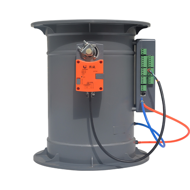
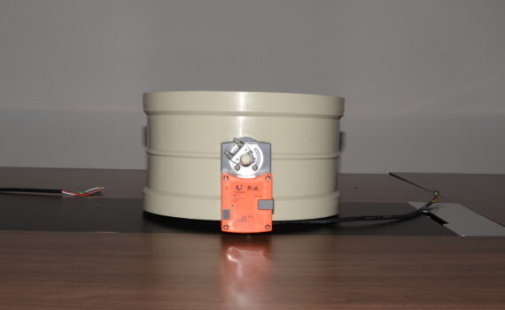
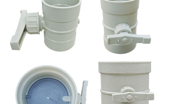
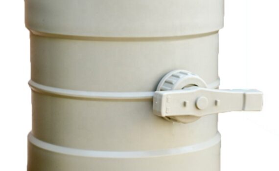
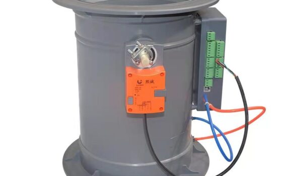
HVAC damper valves are broadly divided into manual and automatic categories based on their actuation method. Manual dampers use a lever, wing nut, or hand quadrant positioned outside the duct to set blade position, providing simple and cost-effective airflow balancing for applications where set-and-forget operation is acceptable—residential branch ducts, small commercial exhaust systems, and static pressure relief applications. Automatic dampers employ electric motor, pneumatic cylinder, or spring-return actuators that respond to control system signals, enabling dynamic airflow modulation in building automation systems, fire safety sequences, and demand-controlled ventilation. The selection between manual and automatic HVAC damper valves depends on whether the application requires remote control, automated response to safety signals, or integration with building management systems. Manual dampers offer zero energy consumption and minimal failure modes but cannot respond to changing conditions. Automatic dampers provide responsive control and system integration capabilities but require power supply, control wiring, and periodic actuator maintenance. In most commercial HVAC systems, a combination of both types is deployed—automatic dampers at major control points and manual dampers for fixed balancing adjustments.

Aluminum Air Damper Valve

How to Choose the Right Damper Valve for Your System

Match Damper Type to Your HVAC System & Application Scenario

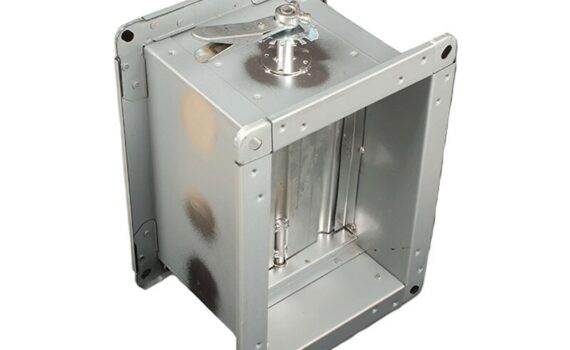
Effective HVAC damper valve selection begins with clearly defining the damper’s functional role within the system. For airflow modulation in variable air volume (VAV) systems, opposed-blade dampers provide superior linear flow characteristics compared to parallel-blade designs. For tight isolation in laboratory exhaust or healthcare isolation room applications, bubble-tight dampers with inflatable blade seals deliver zero-leakage performance that standard HVAC damper valves cannot achieve. For outdoor air economizer systems, barometric or gravity dampers with low-leakage ratings ensure that free cooling opportunities are captured without excessive energy waste. Fire and smoke damper selection must reference the specific fire-resistance rating of the penetrated assembly and the applicable code edition. Documenting the required function, operating conditions, control integration needs, and applicable code requirements in a formal damper schedule—before reviewing manufacturer catalogs—prevents the common error of selecting dampers based on price alone and discovering functional deficiencies after installation.

Size, Pressure Rating & Material Compatibility Checks

Proper HVAC damper valve sizing requires matching the damper face area to the duct cross-section while maintaining face velocities within acceptable ranges—typically 1,000 to 1,500 feet per minute for supply ducts and 500 to 1,000 FPM for return and exhaust applications. The damper frame and blade assembly must be rated for the maximum static pressure encountered in the duct system, including transient pressure spikes during fan startup or emergency ventilation events. Material selection must account for the airstream conditions: galvanized steel is standard for general HVAC applications, stainless steel is required for high-humidity or mildly corrosive environments, and coated or lined dampers are necessary for kitchen exhaust or chemical fume handling ducts. Actuator torque must be calculated based on blade area, operating pressure differential, and seal friction, with a minimum 50 percent safety factor applied. Oversizing actuators adds unnecessary cost, while undersizing actuators results in incomplete closure and increased leakage—both avoidable through proper engineering calculation during the HVAC damper valve specification process.

Total Cost of Ownership: Upfront Cost, Maintenance & Lifespan

Evaluating HVAC damper valves on total cost of ownership rather than purchase price alone reveals that the cheapest damper is rarely the most economical over its service life. A high-quality damper with a premium actuator may cost 30 to 50 percent more upfront but deliver 15 to 20 years of maintenance-free operation, while a budget damper may require actuator replacement within 3 to 5 years and seal replacement every 2 to 3 years—each service event requiring ductwork access, system shutdown, and technician labor. Energy cost implications are equally significant: a damper with AMCA Class I leakage ratings versus Class III can save thousands of dollars annually in a large commercial building through reduced fan energy and improved zone control precision. Factor in the cost of code compliance failures—failed fire damper inspections can trigger occupancy restrictions, liability exposure, and insurance complications—and the value premium for quality HVAC damper valves becomes clear. ENERGY STAR recommends evaluating dampers on a 20-year lifecycle cost basis that includes purchase price, installation labor, energy performance, maintenance frequency, and replacement cost to identify the true lowest-cost option.

HVAC Damper Valve Selection Matrix

ApplicationRecommended Damper TypeActuationLeakage ClassKey Standard
Zone Temperature ControlOpposed-Blade MotorizedElectric ModulatingAMCA Class IASHRAE 90.1
Fire Barrier PenetrationCurtain or Multi-Blade FireFusible Link (Spring)UL 555 ListedNFPA 80
Smoke ControlCurtain Smoke DamperElectric / PneumaticUL 555S ListedNFPA 105
Outdoor Air EconomizerParallel-Blade MotorizedElectric ModulatingAMCA Class I–IIASHRAE 90.1
Exhaust BalancingOpposed-Blade ManualLever / QuadrantAMCA Class IIISMACNA
Kitchen / Corrosive ExhaustStainless Lined LouverElectric On-OffApplication-SpecificIMC / Local Code

Sources: ASHRAE Handbook, NFPA Standards, ENERGY STAR, UL Product Certification.

For a complete range of HVAC damper valves—including zone control, fire and smoke rated, and custom-fabricated models for specialty applications—explore our complete product catalog.


Aluminum Air Damper Valve

Industrial Air Damper Valve for Power Plant & Flue Gas Desulfurization (FGD) Systems: Complete Guide

Power generation facilities face increasingly stringent emission regulations worldwide, with sulfur dioxide (SO₂) limits tightening across every major regulatory jurisdiction. At the heart of compliance lies the flue gas desulfurization system—a complex network of absorbers, scrubbers, and ductwork that removes SO₂ from exhaust gases before they reach the atmosphere. Controlling and directing these massive gas streams through the treatment process requires industrial air damper valves engineered to withstand extreme temperatures, corrosive chemical environments, and continuous high-pressure operation. A single underperforming damper can compromise an entire FGD train, forcing derating, unplanned shutdowns, or regulatory non-compliance with substantial financial penalties. Selecting the right industrial air damper valve for power plant and FGD applications demands a thorough understanding of damper types, material compatibility, sizing methodology, and lifecycle maintenance requirements. This guide provides power plant engineers, maintenance managers, and procurement professionals with a comprehensive resource covering damper fundamentals in FGD contexts, material and type selection for corrosive environments, and proven installation and maintenance practices that maximize equipment longevity and system reliability.

Industrial air damper valve installation in power plant FGD ductwork

Understanding Industrial Air Damper Valves in Power Plant and FGD Contexts

What Are Industrial Air Damper Valves and Their Role in Power Plant Emission Control

Industrial air damper valves are heavy-duty flow control devices installed within ductwork and gas handling systems to regulate, isolate, or redirect large-volume gas streams. In power plant emission control, these valves serve multiple critical functions: they direct flue gas from the boiler through selective catalytic reduction (SCR) systems for NOₓ removal, through electrostatic precipitators or baghouses for particulate control, and through FGD absorbers for SO₂ removal. Bypass dampers allow individual treatment stages to be isolated for maintenance without shutting down the entire generating unit. Isolation dampers seal off hazardous atmospheres during equipment inspections and turnaround activities. The scale of these industrial air damper valves is substantial—units in large coal-fired or gas-fired power plants commonly exceed 3 meters in diameter and must operate reliably across temperature ranges from ambient to 400°C, under differential pressures up to 5 kPa, and in gas streams laden with fly ash, acid mists, and dissolved chlorides. Failure to perform at any point in this chain results in emission exceedances, equipment damage, or safety incidents, making damper reliability a direct contributor to both environmental compliance and plant profitability.

How Flue Gas Desulfurization (FGD) Systems Utilize Air Dampers for Sulfur Dioxide Removal

Flue gas desulfurization systems use industrial air damper valves at multiple control points to manage the complex gas flow paths required for effective SO₂ removal. Raw flue gas enters the FGD ductwork through inlet dampers that regulate flow volume to match absorber capacity across varying boiler loads. Recirculation dampers redirect a portion of treated gas back through the absorber when inlet SO₂ concentrations exceed single-pass removal capacity. Bypass dampers provide the critical function of diverting flue gas around the FGD system during startup, upset conditions, or absorber maintenance, while maintaining continuous boiler operation. Outlet dampers control treated gas discharge to the stack and must maintain tight shutoff to prevent untreated gas from reaching the atmosphere during isolation events. The International Energy Agency (IEA) reports that wet limestone FGD systems—the dominant technology globally—achieve 95 to 99 percent SO₂ removal efficiency, but only when every damper in the gas path performs within specification. Even marginal leakage through a single bypass or isolation damper can reduce overall system removal efficiency below regulatory thresholds, making industrial air damper valve performance a non-negotiable element of FGD system design.

Key Performance Requirements for Air Dampers in Harsh Power Plant Environments

Industrial air damper valves in power plant and FGD service must meet demanding performance criteria that far exceed commercial HVAC damper requirements. Temperature resistance is paramount—dampers upstream of the FGD absorber handle flue gas at 120 to 180°C, while bypass dampers may encounter temperatures exceeding 350°C during emergency diversion events. Corrosion resistance is equally critical, as FGD environments expose damper components to saturated gas streams containing dissolved sulfuric acid, hydrochloric acid, chlorides, and abrasive fly ash particulates at pH levels between 2 and 6. Leakage performance must meet tight classifications—typically AMCA Class I or EN 1751 Class A—to ensure effective gas isolation and emission control. Structural integrity under continuous pressure loading, thermal cycling, and vibration from adjacent equipment must be maintained for service lives exceeding 15 years with appropriate maintenance. Actuation reliability is essential, as dampers must respond to control signals within seconds during load changes or emergency events. The U.S. Environmental Protection Agency (EPA) and equivalent regulatory bodies worldwide require continuous emissions monitoring that validates damper performance indirectly through stack emission data, making any damper-induced system deficiency immediately visible to regulators.

Plastic Air Damper Valve

Types and Selection of Air Damper Valves for FGD Systems

Common Types of Industrial Air Dampers: Butterfly, Louver, and Guillotine Valves for FGD Applications

Three primary damper types dominate industrial air damper valve applications in power plant FGD systems. Butterfly dampers feature a circular disc rotating on a central shaft within a round or rectangular frame, offering compact installation, fast actuation, and good flow control characteristics for ducts up to 2.5 meters in diameter. Louver dampers consist of multiple parallel blades rotating in unison, providing larger flow area coverage and lower pressure drop across the blade array, making them preferred for high-volume flue gas ducts exceeding 3 meters in width. Guillotine dampers use a single solid plate that slides vertically or horizontally into the gas stream, delivering the tightest possible isolation seal with zero blade-through-duct leakage, and are the standard choice for critical isolation applications such as absorber inlet and bypass damper service. Each industrial air damper valve type presents distinct trade-offs: butterfly dampers offer simplicity and cost efficiency but higher leakage at large sizes; louver dampers handle large cross-sections but require more complex linkage systems; guillotine dampers provide superior sealing but demand greater installation space and heavier structural support. Selection depends on duct geometry, required leakage class, operating temperature, and whether the primary function is flow modulation or tight isolation.

Material Selection for Corrosive FGD Environments: Comparing Metals, Alloys, and Plastic Dampers

Material compatibility with the FGD gas environment is the single most important factor determining industrial air damper valve service life. Standard carbon steel dampers corrode rapidly in wet FGD conditions and are unsuitable for any application downstream of the gas cooling section. Stainless steel grades 316L and 317LM offer improved chloride resistance and are commonly used for damper frames and shafts in moderately corrosive zones. For aggressive wet FGD environments where chloride concentrations exceed 10,000 ppm and pH drops below 3, high-performance alloys such as Hastelloy C-276 or Inconel 625 provide the necessary corrosion resistance for damper blades and critical sealing surfaces. Lined dampers—carbon steel shells with internal rubber, fluoropolymer, or glass flake linings—offer a cost-effective alternative where full alloy construction is not economically justified. Plastic and FRP (fiberglass-reinforced plastic) dampers serve niche applications in low-temperature, low-pressure exhaust ducts where metallic options are unnecessary. Seal materials demand equal attention: PTFE-based flexible seals outperform elastomeric gaskets in acid mist environments, maintaining sealing integrity across wider temperature and chemical exposure ranges. The National Association of Corrosion Engineers (NACE) provides material selection guidelines that should be referenced during any industrial air damper valve specification for FGD service.

Sizing and Specification Criteria for Optimal Air Damper Valve Performance in Power Plants

Proper sizing of industrial air damper valves ensures both adequate flow capacity and acceptable pressure drop across the operating range. Damper face velocity should be maintained between 15 and 25 m/s for most FGD duct applications—velocities below 15 m/s risk particulate settling and erosion on horizontal duct sections, while velocities above 25 m/s generate excessive pressure drop and noise. The damper frame and blade assembly must be structurally rated for the maximum differential pressure encountered during worst-case scenarios, including emergency bypass events where pressure differentials can spike to 3 to 5 times normal operating values. Actuator torque selection must account for both aerodynamic forces on the blade and friction forces from seals under operating temperature conditions, with a safety factor of 1.5 to 2.0 applied to calculated torque requirements. Leakage class specification should reference the applicable standard—AMCA 500-D or EN 1751—with the required class determined by the damper’s function in the emission control chain. Critical isolation dampers demand the tightest class, while modulating control dampers may accept higher leakage tolerances where some flow bypass is operationally acceptable. Documenting all sizing calculations, material selections, and performance requirements in a formal damper specification ensures consistent procurement quality and provides the baseline for commissioning verification.

Installation, Operation, and Maintenance of Air Damper Valves in FGD Systems

Step-by-Step Installation Guide for Air Dampers in Power Plant Ductwork and FGD Units

Correct installation of industrial air damper valves directly determines whether laboratory-rated performance translates to field performance. Begin by verifying that the duct opening dimensions match the damper frame within the manufacturer’s tolerance—typically plus or minus 3 mm—and that structural supports are adequate for the damper weight plus dynamic loading from gas flow and seismic events. Lift and position the damper using designated lifting points only, never lifting by the actuator shaft or blade linkage. Secure the frame to the duct flange using high-temperature gasket material and torque all fasteners to specification in a cross-pattern sequence to ensure even compression. Connect the actuator and verify full stroke travel—blade must achieve complete open and closed positions without mechanical binding or over-travel. Install position feedback sensors and confirm signal accuracy against actual blade position at 0, 25, 50, 75, and 100 percent open. Conduct a pre-commissioning leakage test at design operating pressure, documenting results against the specified leakage class. For FGD applications, pay particular attention to drain provisions at the damper frame low point, as condensate accumulation in the frame cavity accelerates corrosion and compromises seal integrity. Complete the installation by applying corrosion-resistant coatings to all exposed fasteners and frame surfaces not protected by internal lining.

Operational Best Practices for Air Damper Valves in FGD Systems to Ensure Efficiency and Compliance

Operational discipline significantly extends industrial air damper valve service life and maintains emission compliance. Avoid holding dampers in partially open positions for extended periods unless specifically designed for modulating service, as intermediate positions expose seal edges to direct gas impingement and accelerated erosion. During boiler load changes, sequence damper movements to prevent sudden pressure surges that stress blade assemblies and actuator linkages. Monitor actuator torque trends over time—a gradual increase in closing torque indicates seal swelling, corrosion buildup, or bearing degradation, providing early warning before leakage becomes measurable. Integrate damper position and torque data into the plant’s distributed control system (DCS) to enable automated alarms when performance parameters deviate from baseline values. During FGD system startups, follow manufacturer-recommended warm-up sequences for hot bypass dampers to prevent thermal shock to blade and frame assemblies. The Electric Power Research Institute (EPRI) publishes operational guidance for FGD damper management that reflects decades of collective utility experience and should be incorporated into plant operating procedures. Consistent operational practices reduce unplanned maintenance events by 30 to 50 percent compared to reactive management approaches.

Maintenance Schedules, Inspection Checklists, and Troubleshooting for Longevity in FGD Applications

A structured maintenance program is essential for maximizing industrial air damper valve service life in corrosive FGD environments. Quarterly inspections should verify actuator operation, check for external corrosion on frames and linkages, and confirm seal condition through visual examination of accessible surfaces. Annual inspections during planned outages should include internal blade and seal inspection, measurement of seal wear against replacement criteria, lubrication of bearings and linkage pivot points, and recalibration of position feedback sensors. Every three to five years, conduct a full leakage test at operating pressure to quantify performance degradation and determine whether seal replacement or blade refurbishment is warranted. Common troubleshooting issues include increased leakage from seal wear or chemical attack, sluggish actuation from bearing corrosion or linkage binding, and uneven blade travel from thermal distortion. Documenting all inspection findings, maintenance actions, and test results in a damper-specific maintenance database enables trend analysis that predicts remaining useful life and optimizes replacement scheduling. For critical isolation dampers, maintain a spare seal kit and actuator on-site to minimize outage duration when repairs are needed. By treating industrial air damper valve maintenance as a proactive, data-driven program rather than a reactive repair activity, power plant operators sustain FGD system performance, extend equipment life, and maintain continuous regulatory compliance.

FGD Damper Application Matrix

Damper LocationRecommended TypeMaterialLeakage ClassTemperature Range
Absorber InletGuillotineHastelloy C-276 / Lined CSAMCA Class I / EN A120–180°C
Absorber OutletButterfly or Louver317LM Stainless SteelAMCA Class I / EN A50–80°C
Bypass DuctGuillotineInconel 625 / 316L SSAMCA Class I / EN A300–400°C
RecirculationButterflyRubber-Lined Carbon SteelAMCA Class II / EN B40–70°C
Stack InletLouver316L Stainless SteelAMCA Class II / EN B50–90°C

Sources: IEA FGD Technology Reports, EPA Emission Guidelines, NACE Material Selection Standards, EPRI FGD Operational Guidance.

For industrial air damper valves engineered for power plant and FGD applications—including high-temperature bypass dampers, corrosion-resistant isolation dampers, and custom-fabricated models for extreme service conditions—explore our complete product catalog.


Air damper leakage standards comparison chart for industrial HVAC compliance

Complete Guide to Air Damper Leakage Standards: AMCA, EN 1751 & ASHRAE 90.1 Compliance

In industrial ventilation, exhaust gas treatment, and commercial HVAC systems, air dampers serve as critical control points that regulate, isolate, and redirect airflow. When dampers fail to seal properly, the consequences extend far beyond minor inefficiency—uncontrolled leakage compromises process control, contaminates adjacent zones, wastes energy, and in hazardous gas handling applications, creates serious safety hazards. The global regulatory landscape addresses these risks through three primary air damper leakage standards: AMCA Standard 500-D in North America, EN 1751 across Europe and international markets, and ASHRAE 90.1 for building energy compliance. Understanding the scope, test methods, leakage classifications, and compliance pathways defined by each standard is essential for engineers, facility managers, and procurement professionals who specify dampers for demanding industrial and commercial applications. This guide provides a comprehensive analysis of these air damper leakage standards, compares their methodologies, and delivers practical guidance on selecting, testing, and implementing compliant dampers across diverse system requirements.

Air damper leakage standards comparison chart for industrial HVAC compliance

Understanding Air Damper Leakage Standards: Fundamentals and Regulatory Framework

Why Air Damper Leakage Standards Are Critical for Industrial and HVAC System Performance

Air damper leakage standards exist because uncontrolled airflow through closed or partially closed dampers creates measurable operational, financial, and safety consequences. In industrial exhaust systems handling corrosive gases such as hydrogen chloride, sulfur dioxide, or volatile organic compounds, a leaking isolation damper can allow hazardous fumes to migrate into occupied work zones, triggering regulatory violations and endangering personnel. In commercial HVAC applications, leaking dampers in outdoor air economizer systems allow conditioned air to escape continuously, increasing energy consumption by 10 to 30 percent according to industry field studies. Without standardized air damper leakage classifications, engineers have no reliable basis for comparing products, specifying acceptable performance, or verifying compliance after installation. The standards framework provides uniform test conditions, defined leakage classes, and repeatable measurement protocols that enable apples-to-apples product comparison and ensure that specified damper performance is achieved in the field, not merely claimed on a datasheet.

Overview of Key Standards: AMCA, EN 1751, and ASHRAE 90.1 – Scope and Application

Three dominant air damper leakage standards govern the global market, each serving a distinct regulatory and geographic scope. AMCA Standard 500-D, published by the Air Movement and Control Association International, defines laboratory test procedures for determining damper leakage rates under controlled pressure differentials and is the primary reference for North American damper manufacturers and specifiers. EN 1751, the European standard for ventilation duct components, establishes leakage classification and test methods applicable across the European Union and adopted by many international markets outside North America. ASHRAE Standard 90.1, the Energy Standard for Buildings Except Low-Rise Residential Buildings, does not prescribe damper test methods but instead defines maximum allowable leakage rates for specific damper applications within building energy codes, creating compliance obligations that reference AMCA or equivalent test data. Together, these three air damper leakage standards form an interconnected framework: AMCA and EN 1751 define how to measure leakage, while ASHRAE 90.1 defines what leakage levels are acceptable for energy code compliance in building systems.

How Leakage Standards Impact Energy Efficiency, Safety, and Global Compliance Requirements

The practical impact of air damper leakage standards operates across three interconnected domains. Energy efficiency is the most quantifiable—ASHRAE 90.1 specifies maximum leakage rates for fire dampers, smoke dampers, and outdoor air dampers precisely because research demonstrates that poorly sealed dampers are among the largest contributors to uncontrolled air leakage in commercial buildings. Safety is the second domain, particularly in industrial settings where dampers isolate toxic, flammable, or explosive gas streams. Here, air damper leakage standards provide the performance benchmarks that determine whether a damper can safely contain hazardous atmospheres during maintenance shutdowns or emergency isolation events. The third domain is global market access—manufacturers seeking to supply dampers internationally must demonstrate compliance with regional air damper leakage standards, requiring independent laboratory testing and certification from recognized bodies. Projects governed by European procurement rules demand EN 1751 classification, North American specifications reference AMCA ratings, and any building pursuing code compliance in the United States must address ASHRAE 90.1 leakage limits. Failure to meet applicable air damper leakage standards can result in project delays, rejected equipment, and liability exposure.

Factory exhaust air control system

In-Depth Analysis of Key Air Damper Leakage Test Standards and Methods

AMCA Standard 500-D: Laboratory Test Procedure for Air Damper Leakage Ratings

AMCA Standard 500-D establishes the definitive laboratory protocol for measuring air damper leakage rates in North America. The standard requires testing at specific static pressure differentials—typically 1 inch w.g. (250 Pa) and 4 inches w.g. (1000 Pa)—with the damper in its fully closed position and all external actuators and linkages installed as they would be in service. Leakage is measured in cubic feet per minute per square foot of damper face area (CFM/ft²) and classified into defined leakage classes, with Class I representing the lowest leakage and Class IV the highest allowable for commercial applications. The test procedure mandates that the damper be installed in a sealed test chamber with calibrated airflow measurement instrumentation, ensuring that results reflect only leakage through the damper assembly itself and not through the test apparatus. AMCA 500-D also requires that manufacturers publish both the leakage class and the specific test pressure at which it was determined, because leakage rates increase non-linearly with pressure differential. This transparency requirement is what makes AMCA-rated air damper leakage data reliable for engineering calculations and specification compliance.

EN 1751: European Standard for Ventilation Ducts – Leakage Classification and Test Methods

EN 1751 serves as the European counterpart to AMCA 500-D, establishing leakage classes and test methods for dampers, valves, and other airflow control devices within ventilation duct systems. The standard defines leakage classifications A through D for low-pressure applications (up to 500 Pa) and additional classifications for medium and high-pressure systems up to 2500 Pa. EN 1751 leakage rates are expressed in liters per second per square meter (L/s/m²) of damper area at specified test pressures, with Class A representing tightest sealing and Class D the most permissive. The test methodology shares fundamental principles with AMCA 500-D—sealed test chamber, calibrated measurement, damper fully closed—but differs in pressure points, leakage rate units, and classification boundaries. EN 1751 also addresses leakage through the damper frame and wall penetration, providing a more comprehensive assessment of installed performance than damper-blade leakage alone. For projects specified under European standards or international contracts referencing EN 1751, manufacturers must provide certified test reports from accredited European laboratories demonstrating compliance with the specified air damper leakage class.

ASHRAE 90.1: Energy Standard for Buildings – Leakage Limits and Compliance Pathways for Air Dampers

ASHRAE 90.1 takes a different approach from the test-focused AMCA and EN 1751 standards by defining prescriptive maximum leakage rates for specific damper applications within building energy codes. Section 6.4.3.4 of the standard requires that outdoor air dampers in economizer systems not exceed 20 CFM/ft² at 1 inch w.g. when fully closed, and that motorized dampers in other applications meet similarly defined limits. Fire and smoke dampers must comply with their own referenced standards (UL 555 and UL 555S respectively) while also meeting the energy performance intent of ASHRAE 90.1. The standard provides two compliance pathways: prescriptive, where specific component performance requirements must be met, and performance, where whole-building energy modeling demonstrates equivalent or better efficiency. For damper specification, the prescriptive path requires documented air damper leakage test data demonstrating compliance with stated limits. ASHRAE 90.1 is adopted by reference into most U.S. state and local building codes, making its air damper leakage requirements legally enforceable rather than merely advisory. International projects seeking LEED certification or other green building ratings also reference ASHRAE 90.1 performance thresholds as benchmarks for energy-efficient damper selection.

industrial dampers

Selecting, Testing, and Implementing Compliant Air Dampers for Industrial Applications

How to Choose Air Dampers Meeting AMCA, EN, or ASHRAE Standards for Your Specific Application

Selecting compliant air dampers requires matching the applicable standard to the project’s regulatory jurisdiction, system function, and operating conditions. For North American commercial HVAC projects, specify AMCA 500-D rated dampers with leakage classes appropriate to the application—Class I for critical isolation, Class II for general outdoor air control, and Class III or IV only where leakage tolerance is high. Verify that published leakage data corresponds to the actual operating pressure differential, not a lower test pressure that understates real-world leakage. For European or international projects, require EN 1751 classification certificates from accredited test laboratories, matching the leakage class to the duct system’s operating pressure class. In all cases, cross-reference against ASHRAE 90.1 prescriptive limits if the project falls under U.S. energy codes. Beyond leakage class, consider actuator torque requirements—insufficient closing torque is the most common cause of field-measured leakage exceeding laboratory ratings—and ensure the selected damper blade and seal materials are compatible with the conveyed airstream’s temperature, humidity, and chemical composition. Requesting third-party certified air damper leakage test reports rather than relying solely on manufacturer-published data provides the highest assurance of compliant performance.

Industrial Case Study: Applying Leakage Standards to Corrosive Gas Handling Systems

A chemical processing facility in Southeast Asia required isolation dampers for a multi-stage exhaust gas treatment system handling hydrogen chloride and chlorine dioxide at temperatures up to 200°C. The engineering specification demanded EN 1751 Class A leakage performance at 1500 Pa operating pressure, combined with full corrosion resistance from damper materials and seals. Standard galvanized steel dampers with elastomer seals were eliminated during evaluation because elastomer gaskets degrade rapidly in halogenated gas service, leading to leakage escalation within 6 to 12 months. The selected solution incorporated dampers constructed from Hastelloy C-276 blades with PTFE-based flexible seals rated for continuous chemical exposure. Independent testing per EN 1751 confirmed Class A leakage at the specified pressure, and post-installation commissioning tests verified field performance within 5 percent of laboratory values. The project demonstrates that achieving air damper leakage standard compliance in aggressive industrial environments requires integrated attention to materials science, seal technology, and test methodology—not merely selecting a damper with a favorable datasheet leakage number.

Installation, Testing, and Certification Best Practices to Ensure Long-Term Compliance with Leakage Standards

Even dampers that meet air damper leakage standards in the laboratory can fail to deliver compliant performance if installed incorrectly. Best practices begin with ensuring the duct opening matches the damper frame dimensions precisely—gaps between the frame and ductwork create bypass leakage paths that no damper blade seal can compensate for. Seal all frame-to-duct connections with high-temperature mastic or gasket material appropriate to the system conditions. Verify actuator stroke adjustment so the damper achieves full closed position without over-travel, which damages seals and increases long-term leakage. After installation, conduct field leakage testing using calibrated airflow measurement equipment at the system’s design operating pressure, comparing results against the specified air damper leakage class. Document all test results, actuator settings, and seal inspections in a commissioning report that becomes part of the facility’s permanent maintenance record. Schedule periodic re-inspection—annually for critical isolation dampers and every three to five years for general service dampers—to detect seal degradation, corrosion, or mechanical wear before leakage exceeds acceptable limits. By treating air damper leakage compliance as a lifecycle management requirement rather than a one-time procurement checkbox, facility operators sustain system performance, energy efficiency, and regulatory compliance throughout the damper’s operational life.

Air Damper Leakage Standards Comparison

ParameterAMCA 500-DEN 1751ASHRAE 90.1
RegionNorth AmericaEurope / InternationalU.S. Building Codes
ScopeLaboratory test methodClassification & test methodPrescriptive leakage limits
Pressure Range1–4 in. w.g. (250–1000 Pa)Up to 2500 Pa1 in. w.g. (250 Pa) typical
Leakage UnitsCFM/ft²L/s/m²CFM/ft²
ClassificationClass I–IVClass A–DApplication-specific limits
Certification BodyAMCA InternationalNational accreditation labsAdopted via building codes
Primary ApplicationProduct rating & specificationProduct rating & specificationBuilding energy compliance

Sources: AMCA Standards, EN 1751 Overview, ASHRAE 90.1, USGBC LEED.

For industrial dampers certified to AMCA, EN 1751, and ASHRAE 90.1 standards—including high-temperature, corrosion-resistant, and custom-fabricated models for exhaust gas treatment and HVAC applications—explore our complete product catalog.


Motorized Air Damper Valve: Electric Actuator vs. Pneumatic Actuator Selection Guide

In modern building automation and industrial process control, motorized air damper valves have become indispensable components for regulating airflow with precision, reliability, and remote operability. The choice between electric and pneumatic actuation represents one of the most critical decisions in specifying these systems, as it directly impacts response speed, control accuracy, installation cost, maintenance requirements, and long-term operational reliability. While electric actuators offer seamless integration with digital building management systems and require only power wiring, pneumatic actuators deliver lightning-fast response times and inherent fail-safe capabilities through spring-return mechanisms. Understanding the fundamental differences between these two actuation technologies — and how they align with specific application requirements — is essential for engineers, facility managers, and procurement specialists tasked with selecting the right motorized air damper valve solution.

This comprehensive guide examines the operating principles, performance characteristics, and application suitability of electric and pneumatic actuators for air damper valve control. It provides a detailed comparison of key parameters such as torque output, response speed, duty cycle, and fail-safe options, alongside practical selection criteria based on system requirements, environmental conditions, and budget constraints. By the end of this article, readers will have a clear framework for evaluating and selecting the optimal actuator type for their motorized air damper valve applications, whether for commercial HVAC systems, industrial process ductwork, fire and smoke control, or cleanroom environments.

Motorized Air Damper Valve with Electric and Pneumatic Actuator Comparison

Understanding Motorized Air Damper Valves: How Actuators Control Airflow

What Is a Motorized Air Damper Valve and How Does It Differ from Manual Damper Valves

A motorized air damper valve is a mechanical device installed in ductwork that controls airflow by opening, closing, or modulating a set of blades using an automated actuator. Unlike manual damper valves, which require physical intervention by personnel to adjust blade position via a hand lever, quadrant, or chain operator, motorized air damper valves can be controlled remotely through building automation systems, programmable logic controllers, or simple on/off switches. This automation capability enables dynamic airflow regulation based on real-time conditions such as temperature, pressure, occupancy, or process requirements, without the need for constant human oversight.

The fundamental difference between motorized and manual air damper valves lies in the actuation mechanism and control philosophy. Manual dampers are typically set during commissioning and left in a fixed position, with occasional adjustments made during maintenance or system rebalancing. In contrast, motorized dampers can continuously modulate to match changing loads, respond automatically to fire or smoke detection signals, and be integrated into complex control sequences that optimize energy efficiency and occupant comfort. For applications requiring frequent adjustment, precise positioning, or emergency response — such as variable air volume systems, smoke control zones, or process exhaust systems — motorized air damper valves are the preferred solution. The actuator itself is the “brain” of the system, converting electrical or pneumatic energy into the precise rotational motion required to drive the damper blades to their target position.

How Electric and Pneumatic Actuators Convert Energy into Precise Air Damper Valve Movement

Electric and pneumatic actuators convert different forms of energy into the mechanical torque required to rotate the damper blade shaft, but their operating principles are fundamentally distinct. An electric actuator uses an electric motor to drive a gearbox that reduces speed and increases torque, translating electrical energy into controlled rotational motion. The motor is controlled by an input signal — commonly 0-10V, 4-20mA, 2-10V, or digital protocols like Modbus or BACnet — that specifies the desired blade position. The actuator’s internal electronics compare the actual position with the target position and adjust the motor accordingly until the error is minimized.

A pneumatic actuator, by contrast, uses compressed air as its energy source. The most common type is the rack-and-pinion design, where compressed air enters a cylinder and pushes against a piston, which drives a rack gear that rotates the pinion gear attached to the damper shaft. Spring-return pneumatic actuators include a mechanical spring that automatically drives the damper to a safe position when air supply is lost — a critical feature for fire and smoke control applications. Pneumatic actuators are controlled by solenoid valves that direct air flow to one side by a separate positioner or sensor. The key advantage of pneumatic actuation is the high force density and rapid response, while electric actuation excels in precision and ease of integration with digital control systems.

Key Actuator Performance Parameters: Torque Output, Speed, Duty Cycle, and Fail-Safe Options

When selecting a motorized air damper valve actuator, four performance parameters are critical: torque output, rotational speed, duty cycle, and fail-safe capability. Torque output — measured in Newton-meters — must exceed the maximum torque required to move the damper blade against the differential pressure acting across it, with a safety margin typically of 1.5 to 2.0 times. Under-sizing the actuator results in incomplete blade travel, premature motor burnout, or seized dampers. Rotational speed — measured in seconds per 90-degree stroke — determines how quickly the damper can respond to control signals. Electric actuators typically require 15 to 60 seconds for a full stroke, while pneumatic actuators can complete the same motion in 1 to 5 seconds.

Duty cycle defines the percentage of time the actuator can operate continuously without overheating or exceeding its service life. Standard actuators are rated for 50% to 100% duty cycle, with continuous modulation requiring 100% duty cycle ratings. Fail-safe options are essential for life safety applications, as defined by NFPA 90A and the International Mechanical Code (IMC). Spring-return pneumatic actuators provide inherent fail-safe operation, while electric actuators require battery backup, supercapacitors, or mechanical spring systems to achieve the same function. The following table summarizes typical actuator performance ranges:

ParameterElectric ActuatorPneumatic Actuator
Torque Range10 to 500+ Nm10 to 2000+ Nm
Stroke Time (90°)15 to 60 seconds1 to 5 seconds
Duty Cycle25% to 100%100% (continuous operation)
Fail-Safe OptionsSpring return, battery backupSpring return (inherent)
Control Signal0-10V, 4-20mA, Modbus, BACnetSolenoid valve, positioner
Power Requirement24VAC/DC, 120VAC, 240VACCompressed air 40-80 psi
PP Air Valve

Electric Actuator vs. Pneumatic Actuator: How They Work and Where Each Excels

Electric Actuator Air Damper Valves: Operating Principle, Power Requirements, and Control Signal Compatibility

Electric actuator air damper valves are the dominant choice in commercial building HVAC systems due to their ease of integration with digital building management systems and their minimal infrastructure requirements. An electric actuator operates by converting electrical energy into mechanical torque through a motor and gearbox assembly. The motor receives a control signal from the BMS or local controller, and the actuator’s internal circuitry drives the motor to the commanded position, using feedback from a position sensor to ensure accuracy. This closed-loop control enables precise modulation of damper blade position, making electric actuators ideal for applications requiring fine control of airflow, such as VAV terminal units, economizer dampers, and zone control dampers.

Electric actuators are available in a wide range of power configurations to match different applications. Low-voltage actuators (24VAC or 24VDC) are standard in HVAC systems, offering safe operation and compatibility with common control voltages. High-voltage actuators (120VAC or 240VAC) are used for larger dampers or industrial applications where higher torque is required. Control signal compatibility is a key advantage of electric actuators: they accept a variety of input types, including analog signals for proportional control, digital on/off signals for two-position control, and communication protocols such as Modbus RTU or BACnet MS/TP for integration with sophisticated automation systems. This versatility allows electric actuator air damper valves to serve as intelligent nodes within a connected building or industrial network, providing real-time position feedback and enabling remote diagnostics and optimization. For detailed product specifications and compatibility information, visit https://ppairvalve.com/.

Pneumatic Actuator Air Damper Valves: Compressed Air Operation, Response Speed, and Force Characteristics

Pneumatic actuator air damper valves are favored in industrial process applications, heavy-duty HVAC systems, and life safety installations where rapid response, high force, and inherent fail-safe capability are paramount. A pneumatic actuator operates by directing compressed air into a cylinder, where it exerts pressure on a piston connected to a rack-and-pinion or scotch-yoke mechanism that rotates the damper shaft. The actuator is controlled by a solenoid valve that switches air flow to one side of the piston or the other, causing the damper to open or close. Spring-return pneumatic actuators include a mechanical spring that automatically drives the damper to a safe position when the compressed air supply is interrupted — a critical feature for fire and smoke control dampers where loss of power or air supply must not compromise life safety.

The force characteristics of pneumatic actuators are a key advantage in large-diameter duct applications. Compressed air at 40 to 80 psi can generate substantial torque, allowing pneumatic actuators to operate dampers with blade areas exceeding several square meters. This high force density makes pneumatic actuators the preferred choice for guillotine dampers, large louver dampers, and industrial butterfly dampers in flue gas systems. Response speed is another major advantage: pneumatic actuators typically complete a 90-degree stroke in 1 to 5 seconds, compared to 15 to 60 seconds for electric actuators. This rapid response is essential for applications requiring quick isolation or redirection of gas streams, such as emergency shutdown sequences or process batch changes. The primary limitation of pneumatic actuators is the requirement for compressed air infrastructure, which adds complexity and cost to the installation.

Factory exhaust air control system

Key Differences Compared: Accuracy, Speed, Cost, Maintenance, and Environmental Suitability

The choice between electric and pneumatic actuation depends on a careful comparison of performance attributes, cost, and environmental suitability. Accuracy is typically superior with electric actuators, which can achieve position repeatability within ±1% or better using closed-loop control. Pneumatic actuators, especially those without positioners, may have repeatability of ±3% to ±5%, though high-precision pneumatic positioners can narrow this gap. Speed favors pneumatic actuators, with response times 5 to 10 times faster than electric actuators — a critical advantage for emergency isolation and rapid process control.

Cost considerations vary by application. Electric actuators generally have lower initial costs for small to medium dampers under 100 Nm torque and require only electrical wiring, eliminating the need for compressed air infrastructure. Pneumatic actuators may have higher initial costs for small dampers but become cost-competitive or superior for large dampers requiring high torque. Maintenance requirements differ significantly: electric actuators are largely maintenance-free for years, with only periodic inspection of connections and seals, while pneumatic actuators require regular inspection of air lines, filters, and solenoid valves to prevent moisture or debris from causing sluggish operation. Environmental suitability also varies: electric actuators are sensitive to extreme temperatures, humidity, and corrosive atmospheres unless specifically rated for harsh conditions, while pneumatic actuators are inherently robust in dirty, hot, or explosive environments where electric motors might fail. The following table provides a direct comparison:

FactorElectric ActuatorPneumatic Actuator
AccuracyExcellent (±1%)Good to excellent (±1–5%)
SpeedSlow (15–60 sec)Fast (1–5 sec)
Initial Cost (small dampers)LowerHigher
Initial Cost (large dampers)HigherLower
MaintenanceLow (periodic inspection)Moderate (air system upkeep)
Environmental SuitabilitySensitive to temp, moistureRobust in harsh conditions
Infrastructure RequiredElectrical wiring onlyCompressed air system

Choosing the Right Actuator for Your Motorized Air Damper Valve Application

Application-Based Selection Guide: HVAC, Industrial Process, Fire and Smoke Control, and Cleanroom Systems

Different applications have distinct requirements that favor either electric or pneumatic actuation. In commercial HVAC systems — including office buildings, hospitals, hotels, and retail spaces — electric actuator air damper valves dominate due to their compatibility with BMS integration, quiet operation, and ease of installation. Variable air volume systems, economizer dampers, and zone control dampers all benefit from the precise modulation capability and digital communication features of electric actuators, as guided by ASHRAE Standard 90.1 for energy efficiency and SMACNA duct construction standards for system design. In industrial process applications — including power plants, chemical facilities, and manufacturing plants — pneumatic actuator air damper valves are often preferred for their high torque output, rapid response, and suitability for harsh environments where dust, temperature extremes, and corrosive atmospheres would challenge electric actuators.

Fire and smoke control systems present a unique case where both actuator types are used, but with different considerations. Pneumatic spring-return actuators are the gold standard for life safety dampers because they provide inherent fail-safe operation — the damper automatically closes upon loss of air supply, regardless of electrical power status. This requirement is codified in NFPA 92 for smoke control systems and the International Building Code (IBC). Electric actuators can also serve in fire and smoke control applications when equipped with battery backup or mechanical spring-return mechanisms, but they require more complex installation and periodic testing of backup power systems. Cleanroom systems used in pharmaceutical, semiconductor, and biotech facilities typically favor electric actuators for their clean operation, precise control, and compatibility with automated monitoring systems that track damper position and air quality parameters.

Decision Checklist: Air Supply Availability, Control System Integration, Budget, and Safety Requirements

Selecting the optimal actuator type requires a systematic evaluation of four key factors. Air supply availability is the first checkpoint: if a compressed air system already exists in the facility, pneumatic actuation becomes a straightforward choice. If no compressed air is available, the cost of installing a compressor, air treatment equipment, and distribution piping must be factored into the decision — often making electric actuation more economical. Control system integration is the second factor: if the application requires integration with a BMS using digital protocols like BACnet or Modbus, electric actuators provide native support. For simple on/off control or applications where the damper is controlled by a standalone controller, both actuator types are viable.

Budget considerations must include not only the initial purchase price but also installation costs, energy consumption, and lifecycle maintenance. Electric actuators typically have lower installation costs for small to medium dampers but may require more expensive controllers for advanced functionality. Pneumatic actuators require investment in compressed air infrastructure but may offer lower lifecycle costs for large dampers in harsh environments. Safety requirements are paramount for life safety applications: fire and smoke control dampers must meet NFPA and IBC codes, which mandate fail-safe operation. Pneumatic spring-return actuators inherently satisfy this requirement, while electric actuators must be specifically equipped with fail-safe mechanisms. The following checklist summarizes the decision process:

Decision FactorElectric Actuator PreferredPneumatic Actuator Preferred
Compressed Air Available?NoYes
Control Integration Needed?BMS / digital protocolsSimple on/off or local control
Budget PriorityLower initial costLower lifecycle cost for large dampers
Response Speed Critical?No (15–60 sec acceptable)Yes (1–5 sec required)
Fail-Safe Required?With backup power/springInherent spring-return
EnvironmentClean, controlled temperatureHarsh, dirty, explosive, extreme temp

Installation, Wiring, and Commissioning Best Practices for Electric and Pneumatic Air Damper Valve Actuators

Proper installation and commissioning are essential to ensure that motorized air damper valves deliver the performance, reliability, and safety required by the application. For electric actuator air damper valves, installation begins with verifying that the actuator torque rating exceeds the calculated torque requirement for the damper at maximum differential pressure. The actuator must be mounted securely to the damper frame using the provided hardware, with the drive shaft properly aligned to the damper shaft to avoid binding or uneven wear. Electrical wiring must comply with local codes and manufacturer specifications, with power wiring sized for the actuator’s current draw and control wiring shielded to prevent interference in noisy environments. Compliance with UL 60730 for automatic controls and ISA 72.02.01 for industrial automation ensures safety and reliability.

Commissioning electric actuators involves verifying that the damper travels through its full stroke without obstruction, that the position feedback accurately reflects the actual blade position, and that the control signal response is linear and repeatable. For BMS integration, the actuator’s communication settings must be configured to match the controller per the BACnet protocol standard. For pneumatic actuator air damper valves, installation requires careful attention to the compressed air supply: air lines must be sized for adequate flow, filters and regulators must be installed to remove moisture and debris, and the air pressure must be set to the manufacturer’s specification. The actuator must be mounted with adequate clearance for the cylinder and spring housing, and the air lines must be routed to avoid kinking or abrasion.

Commissioning pneumatic actuators involves verifying that the air supply is clean and at the correct pressure, that the solenoid valves switch air flow correctly, and that the damper moves smoothly through its stroke. For spring-return actuators, the fail-safe action must be tested by interrupting the air supply and confirming that the damper moves to the designated safe position. Both electric and pneumatic actuators benefit from post-commissioning documentation, including wiring diagrams, air line schematics, and calibration records, which are essential for future maintenance and troubleshooting. Manufacturers such as https://ppairvalve.com/ provide detailed installation guides and commissioning procedures for their motorized air damper valve products, ensuring that customers can achieve optimal performance from day one.


Air Damper Valve Types Explained: Butterfly, Louver, Guillotine, Diverter & Disc Valves Compared

In every industrial plant, power station, chemical facility, and commercial HVAC system, the movement of air and gas through ductwork must be controlled — regulated, isolated, redirected, or stopped entirely. The device that performs these functions is the air damper valve, and selecting the wrong type for a given application can result in excessive leakage, premature failure, dangerous pressure surges, or wasted fan energy that compounds over decades of operation. Despite their critical role, air damper valve selection is frequently based on habit or price rather than a rigorous evaluation of each type’s sealing performance, pressure drop, actuation requirements, and compatibility with the operating environment.

The spectrum of air damper valve types available today is broad: butterfly valves for high-volume flow modulation, louver dampers for uniform distribution across large cross-sections, guillotine dampers for total isolation in harsh industrial ducts, diverter valves for redirecting gas streams between process paths, and disc valves for precision regulation in specialized applications. Each type has a distinct mechanical design, performance envelope, and application sweet spot. Understanding these differences is essential for engineers and facility operators responsible for specifying, installing, and maintaining ductwork systems. This article provides a comprehensive comparison of all major air damper valve types, covering design principles, performance data, application profiles, and a practical selection checklist to guide material and type decisions for every project.

Air Damper Valve Types Including Butterfly, Louver, Guillotine, Diverter, and Disc Valves

Understanding Air Damper Valves: Function, Classification, and Why Valve Type Matters

What Is an Air Damper Valve and How Does It Control Airflow in Industrial and HVAC Systems

An air damper valve is a mechanical device installed within or at the termination of a duct that controls the volume, direction, or passage of air and gas by opening, closing, or modulating a set of movable elements — blades, plates, or discs — within a fixed frame. When the movable element is fully open, air passes through the duct with minimal restriction. When fully closed, the element seals against the frame and adjacent surfaces to block airflow. At intermediate positions, the air damper valve modulates the flow rate, creating a variable resistance that the system fan, natural draft, or process pressure must overcome.

In HVAC systems, air damper valve units balance airflow across branch ducts, modulate supply and return air in variable air volume systems, and isolate duct sections during maintenance. In industrial systems, they regulate flue gas flow in power plants, isolate reactors during chemical batch changes, redirect exhaust streams between treatment trains, and provide tight shut-off during emergency conditions. The operating conditions in industrial applications — temperatures exceeding 500°C, corrosive acid gases, abrasive fly ash, and duct diameters of 5 to 10 meters — demand air damper valve designs far more robust than the lightweight volume dampers used in commercial ventilation. Specialized manufacturers such as https://ppairvalve.com/ engineer each air damper valve for its specific service conditions, ensuring that the mechanical design, material selection, and actuation system are matched to the temperature, chemistry, pressure, and duty cycle of the application.

Plastic Air Damper Valve

Air Damper Valve Classification: Isolation, Regulation, and Diverting Functions Explained

Air damper valve types are classified by their primary function into three categories: isolation, regulation, and diverting. Isolation dampers are designed to provide a complete blockage of airflow when closed, enabling maintenance access, process separation, or emergency containment. The guillotine damper is the gold standard for isolation because its solid plate creates a positive, face-to-face seal with minimal leakage. Isolation air damper valve units must achieve tight leakage classes — Class I or II per AMCA Standard 500 — and must remain operable after extended periods in the open position without seizing due to corrosion, scale buildup, or bearing degradation.

Regulation dampers modulate airflow to a desired rate by positioning the movable element at an intermediate angle. Butterfly and louver dampers are the most common regulation air damper valve types, offering continuous adjustment from fully open to fully closed with flow characteristics that can be linearized through blade profiling or control system compensation. Diverting dampers redirect airflow from one duct path to another — for example, switching a gas stream from an operating scrubber to a standby unit, or directing exhaust to a stack or a heat recovery system. Diverter valves and multi-way dampers serve this function, using two or more passages controlled by a single or linked set of movable elements. The following table summarizes this classification:

ClassificationPrimary FunctionTypical Air Damper Valve TypesKey Requirement
IsolationComplete airflow blockageGuillotine, butterfly (triple offset)Low leakage, reliable closure
RegulationContinuous flow modulationButterfly, louver, discLinear flow characteristic
DivertingRedirect airflow between pathsDiverter, Y-damper, multi-waySynchronized multi-port control

Key Performance Parameters: Leakage Class, Temperature Rating, and Pressure Drop Across Air Damper Valve Types

Specifying an air damper valve requires precise definition of three performance parameters that determine the valve’s ability to survive and function in its intended service. Leakage class — defined by AMCA Standard 500 or equivalent standards such as through the closed air damper valve at a stated differential pressure. Class I, with a leakage rate of 3 CFM per square foot or less at 1 inch water gauge, represents the tightest seal and is required for isolation and emission-critical applications. Class IV, at 30 CFM per square foot, is acceptable only for coarse draft control where some leakage is tolerable.

Temperature rating defines the maximum gas temperature the air damper valve can withstand continuously, with typical ratings ranging from 250 degrees Celsius for standard service to 600 degrees Celsius for flue gas applications and up to 1000 degrees Celsius for specialized high-temperature installations such as bypass dampers upstream of heat recovery steam generators. Material selection, bearing design, and seal materials must all be compatible with the rated temperature. Pressure drop — the static pressure loss created by the air damper valve in its fully open position — directly affects fan energy consumption. Butterfly valves create the lowest pressure drop among damper types because the thin disc presents minimal obstruction. Guillotine plates, when fully retracted, also create minimal pressure drop, but the plate housing adds duct length. Louver dampers create moderate pressure drop proportional to the number of blades and their aspect ratio. The following table compares typical performance parameters across air damper valve types:

ParameterButterflyLouverGuillotineDiverterDisc
Leakage Class (best achievable)Class I (triple offset)Class IClass IClass I–IIClass II
Max TemperatureUp to 1000°CUp to 600°CUp to 1000°CUp to 600°CUp to 500°C
Pressure Drop (fully open)LowModerateVery lowModerateModerate
Max Duct SizeUp to 7m+Up to 10m+Up to 10m+Up to 3mUp to 1m
Actuation ForceModerateLow to moderateHighModerateLow
polypropylene duct damper

Air Damper Valve Types Explained: Butterfly, Louver, Guillotine, Diverter, and Disc Valves

Butterfly and Louver Air Damper Valves: High-Volume Flow Control for HVAC and Process Ductwork

The butterfly air damper valve is the most versatile and widely used damper type in both HVAC and industrial applications. It consists of a circular disc mounted on a central shaft that rotates within a frame installed across the duct cross-section. When the disc is parallel to airflow, the valve is fully open; when perpendicular, it is fully closed. The butterfly air damper valve occupies minimal axial space — typically only the disc thickness plus clearance — making it ideal for retrofit installations and large-diameter ductwork where space is at a premium. The triple offset butterfly design, with three geometric offsets between disc and seat, eliminates rubbing contact during operation and achieves metal-to-metal sealing with leakage rates approaching Class I, making it the premium choice for applications requiring both regulation and tight isolation.

The louver air damper valve uses multiple parallel blades linked together within a rectangular frame, providing more uniform flow distribution across large rectangular duct cross-sections than a single butterfly disc can achieve. Louver dampers are preferred for air handling unit inlet and outlet control, economizer dampers, and large rectangular exhaust openings where a butterfly geometry is impractical. Each blade seals independently against the frame and adjacent blades, and the overall leakage performance depends on the number of blades, seal quality, and blade aspect ratio. Louver air damper valve units are available in parallel-blade and opposed-blade configurations: parallel blades rotate in the same direction and are simpler and less expensive, while opposed blades rotate in opposite directions, providing more linear flow control and tighter sealing at partial closure.

Guillotine Air Damper Valves: Total Isolation and Shutoff in Large-Diameter Industrial Duct Systems

The guillotine air damper valve is the preferred choice when absolute isolation is the primary requirement. It consists of a solid rectangular plate that slides vertically or horizontally into a sealed housing across the duct cross-section, creating a positive, face-to-face seal between the plate and the frame. Unlike butterfly or louver dampers, where sealing depends on the contact pressure between a rotating blade and a curved or flat seat, the guillotine damper’s plate presses directly against the frame, achieving the lowest leakage rates of any air damper valve type — Class I or better — even in large-diameter ducts where other damper types struggle to maintain uniform seal contact.

Guillotine dampers are specified for applications API 598 — specifies the maximum allowable gas leakage requiring total gas sh Efficiency, Pressure Drop, and Actuation Requirements Across Air Damper Valve Types

The performance differences between air damper valve types are significant and directly impact system efficiency, safety, and operating cost. The following table provides a comprehensive head-to-head comparison across the metrics that matter most to system designers and operators:

Performance MetricButterflyLouverGuillotineDiverterDisc
Sealing EfficiencyHigh (triple offset: very high)Moderate to highHighestHighModerate to high
Pressure Drop (open)LowModerateVery lowModerateModerate
Modulation CapabilityExcellentGoodPoor (on/off only)LimitedExcellent
Space RequirementVery compactModerateLarge (retract housing)ModerateCompact
Actuation TorqueModerateLow to moderateHigh (friction on seals)ModerateLow
Maintenance AccessGood, inline service possibleModerateGood, plate removableModerateGood
Cycle LifeHigh (triple offset: very high)ModerateModerate (wear on seals)ModerateHigh
Max Practical SizeUp to 7m+Up to 10m+Up to 10m+Up to 3mUp to 1m
Cost (relative)ModerateModerate to highHighHighLow

This comparison demonstrates that no single air damper valve type is optimal for every application. Butterfly valves offer the best overall versatility — combining compact design, low pressure drop, excellent modulation, and tight sealing in a single package. Guillotine dampers provide unmatched isolation but sacrifice modulating capability and require significant space. Louver dampers excel in large rectangular cross-sections. Diverter valves serve unique flow-redirection functions. And disc valves deliver precision regulation in small-diameter systems.

Best Air Damper Valve Types by Application: Power Generation, HVAC, Chemical Processing, and Mining

Different industries have different air damper valve requirements, and the optimal type varies by application. In power generation, butterfly and guillotine dampers dominate: butterfly air damper valve units regulate flue gas flow at boiler outlets, FGD inlets, and SCR reactors, while guillotine dampers provide total isolation at stack bases and bypass paths. Triple offset butterfly designs are specified where both regulation and tight shut-off are required in a single device.

In HVAC systems, louver dampers control large rectangular air handling unit openings, butterfly dampers modulate branch ducts, and lightweight motorized butterfly air damper valve units serve variable air volume terminals. In chemical processing, butterfly and guillotine dampers handle corrosive exhaust streams, with material selection — stainless steel, alloy-clad, or plastic-lined — matched to the specific chemical environment. In mining and cement plants, heavy-duty butterfly air damper valve units with abrasion-resistant coatings control dust-laden gas flows where standard dampers would erode within months. The following table summarizes application-specific recommendations:

ApplicationRecommended Air Damper Valve TypeKey Requirement
Power Plant Flue GasButterfly (triple offset) + GuillotineHigh temp, low leakage, isolation
HVAC Air HandlingLouver + ButterflyLow pressure drop, modulation
Chemical ExhaustButterfly (alloy or PP lined)Corrosion resistance, tight seal
Mining / CementButterfly (abrasion-resistant)Erosion resistance, heavy-duty
Incinerator Flue GasGuillotine + ButterflyIsolation, acid resistance
Laboratory FumeDisc or small butterflyPrecision regulation, compact
Stack BypassGuillotineTotal isolation, high temperature

Selection Checklist: How to Match Air Damper Valve Type to Temperature, Media, Duct Size, and Budget

Selecting the correct air damper valve requires a systematic evaluation of the application conditions. The following checklist guides engineers through the decision process:

Step 1 — Define the function. Is the primary purpose isolation, regulation, or diversion? This single decision narrows the field to one or two candidate air damper valve types. Isolation demands guillotine or triple offset butterfly. Regulation demands butterfly, louver, or disc. Diversion demands a Y-diverter or multi-way configuration.

Step 2 — Define the operating conditions. What is the maximum gas temperature? What chemicals are present in the gas stream? What is the duct size and shape — round or rectangular? What is the maximum differential pressure across the closed air damper valve? These parameters determine the material, seal type, bearing design, and structural requirements.

Step 3 — Define the performance requirements. What leakage class is required — Class I for tight isolation, or Class IV for coarse draft control? Is modulating control needed, or is on-off operation sufficient? What actuation type is preferred — manual, electric, pneumatic, or hydraulic? Does the actuator require fail-safe positioning upon power loss?

Step 4 — Verify code compliance. Does the application fall under NFPA, IBC, or other regulatory requirements that mandate specific damper ratings or materials? Is a UL listing required? These requirements may eliminate certain air damper valve types or materials from consideration.

Step 5 — Evaluate lifecycle cost. Compare not just the initial purchase price but the total cost of ownership over the damper’s expected service life, including installation labor, actuation hardware, maintenance frequency, seal replacement, and the cost of unplanned downtime if the damper fails. A higher-cost air damper valve with a longer service life and lower maintenance burden often delivers a lower total cost than a cheaper alternative that requires frequent repair or premature replacement. For corrosive environments where metal dampers degrade rapidly, specialized plastic-lined or alloy-constructed air damper valve solutions — available from manufacturers such as https://ppairvalve.com/ — can dramatically extend service life and reduce lifecycle cost.


PP Air Valve

The Complete Guide to Air Damper Types: Volume, Fire, Smoke, Backdraft & Motorized Dampers Explained

Every HVAC system, ventilation network, and smoke control installation depends on air dampers to regulate, direct, and — when necessary — stop the movement of air through ductwork. Despite their critical role, air dampers are among the most frequently misunderstood components in building mechanical systems. Engineers and facility managers often specify dampers based on habit or price rather than a rigorous evaluation of the damper’s function, rating, and compatibility with the application. The consequences of a mismatched air damper range from inefficient airflow balancing and wasted fan energy to catastrophic fire spread through unprotected duct penetrations.

The world of air dampers encompasses a broad spectrum of types, each engineered for a specific purpose. Volume control dampers regulate airflow rate for system balancing. Fire dampers stop the passage of flame through fire-rated barriers. Smoke dampers resist the passage of smoke to maintain tenable evacuation conditions. Backdraft dampers prevent reverse airflow in exhaust and gravity systems. Motorized dampers enable automated, remote, and building-management-integrated control. Understanding the differences between these hvac damper types and functions — their construction, ratings, installation requirements, and maintenance needs — is essential for anyone responsible for specifying, installing, or maintaining ductwork systems. This guide provides a complete reference across all major air damper types, with practical selection criteria, code requirements, and lifecycle considerations drawn from leading industry standards.

Air Damper Types Including Volume

Understanding Air Damper Fundamentals: Function, Structure, and Classification

What Is an Air Damper and How Does It Control Airflow in HVAC Systems

An air damper is a mechanical device installed inside or at the termination of a duct that controls the volume, direction, or passage of air by opening, closing, or modulating a set of blades (also called vanes or louvers) within a frame. When the blades are fully open, air passes through the duct with minimal restriction. When fully closed, the blades seal against the frame and each other to block airflow. At intermediate positions, the air damper modulates the flow rate, creating a variable resistance that the system fan must overcome.

In HVAC systems, air dampers serve multiple functions simultaneously. They balance airflow distribution across branch ducts, ensuring that each zone receives its designed supply volume. They modulate supply and return air to match real-time heating and cooling loads in variable air volume (VAV) systems. They isolate duct sections during maintenance or zone shutdown. And in life safety applications, they automatically close to prevent fire and smoke from spreading through the duct network to other building compartments. The automatic damper types used in modern buildings are sophisticated mechanical assemblies that must meet stringent performance, leakage, and durability standards defined by organizations such as UL (Underwriters Laboratories) and ASHRAE. Selecting the wrong type — or installing the right type incorrectly — can compromise the entire system’s performance and safety.

Key Components of an Air Damper: Blades, Frames, Linkages, and Actuators

Every air damper, regardless of type, consists of four fundamental components that work together to control airflow. The frame is the structural housing that mounts inside or on the duct, providing the sealing surface against which the blades close. Frames are typically constructed from galvanized steel, stainless steel, aluminum, or — for corrosive environments — polypropylene or other thermoplastics. The frame must be rigid enough to resist duct pressure without deflection, as any distortion creates gaps that leak air even when the damper is fully closed.

The blades are the movable elements that rotate within the frame to open or close the airflow path. Blade design varies by damper type: parallel blades rotate in the same direction and are used in volume damper vs balancing damper applications where low leakage is less critical; opposed blades rotate in opposite directions, creating a tighter seal and providing more linear flow control, making them preferred for modulating applications. Each blade is fitted with a seal — typically an elastomeric gasket or metal edge seal — that contacts the frame and adjacent blades when the damper is closed, minimizing leakage. The linkage connects all blades to a common operating shaft, ensuring synchronized rotation. Linkages may be internal (concealed within the frame) or external (mounted on the frame exterior), and they transmit the actuating force from the operator to the blades. The actuator provides the motive force to open and close the damper. Actuators may be manual (lever or hand quadrant), electric (motor-driven), pneumatic (cylinder-operated), or fusible-link-activated (for fire dampers). The choice of damper actuator types depends on the application: manual actuators for simple balancing, electric or pneumatic for automated control, and fusible links for life safety functions.

Air Damper Classification by Function: Control Dampers, Life Safety Dampers, and Combination Dampers

Air dampers are classified into three broad functional categories, each governed by different standards and code requirements. Control dampers — including volume control dampers and modulating dampers — are designed to regulate airflow under normal operating conditions. They are rated for leakage class per ASHRAE Standard 171 (formerly AMCA 500-D), with leakage classes ranging from Class I (lowest leakage, ≤3 CFM/ft² at 1″ w.g.) to Class IV (highest acceptable leakage for general HVAC). Control dampers are not rated for fire resistance and must not be used as substitutes for fire or smoke dampers.

Life safety dampers — including fire dampers, smoke dampers, and combination fire smoke dampers — are designed to protect building occupants by preventing the spread of fire and smoke through duct penetrations in fire-rated barriers. These dampers are tested and listed by UL under specific standards: UL 555 for fire dampers, UL 555S for smoke dampers, and UL 555C for combination fire smoke dampers. They must be installed in compliance with NFPA 80 (fire dampers) and NFPA 105 (smoke dampers). Combination dampers integrate both control and life safety functions in a single assembly — for example, a combination fire smoke damper that modulates airflow during normal operation and closes automatically upon detection of fire or smoke. The following table summarizes this classification:

CategoryFunctionKey StandardRating SystemTypical Application
Control DampersAirflow regulation and balancingASHRAE 171 / AMCA 500-DLeakage Class I–IVHVAC ductwork, VAV systems
Fire DampersBlock flame passage through fire barriersUL 555 / NFPA 80Fire rating (1.5 hr, 3 hr)Duct penetrations in fire walls
Smoke DampersBlock smoke passage through smoke barriersUL 555S / NFPA 105Leakage Class I at 250°FSmoke compartments, stairwells
Combination DampersFire + smoke protection in one unitUL 555CFire + smoke ratingHigh-rise buildings, hospitals

Air Damper Types Explained: Volume, Fire, Smoke, Backdraft, and Motorized Dampers

Volume Control Dampers: Regulating Airflow Rate and Balancing Duct Systems

Volume control dampers are the most common type of air damper in HVAC systems and are installed at branch takeoffs, main duct sections, and individual zone connections to regulate airflow distribution. The volume damper vs balancing damper distinction is often confused, but they serve different purposes: a volume control damper is a general-purpose damper used to adjust flow in any duct section, while a balancing damper is a precision instrument with a calibrated blade position indicator, designed specifically for system air balancing per ASHRAE Standard 111. Balancing dampers allow the commissioning engineer to set and lock each branch to its designed airflow volume, ensuring that the system delivers the correct amount of air to every zone.

Volume control dampers are available in parallel-blade and opposed-blade configurations. Parallel-blade dampers are simpler and less expensive but provide less linear flow control and higher leakage at partial closure. Opposed-blade dampers offer more uniform airflow distribution across the duct cross-section and better modulation characteristics, making them preferred for VAV applications where the damper must operate at intermediate positions for extended periods. Leakage performance is critical: ASHRAE 171 defines four leakage classes, with Class I representing the tightest seal (≤3 CFM/ft² at 1″ w.g.) and Class IV the loosest (≤30 CFM/ft²). For energy-efficient systems, Class I or II dampers are recommended to minimize the conditioned air wasted through closed or partially closed dampers.

Fire Dampers and Smoke Dampers: How They Protect Life Safety and Building Integrity

Fire dampers and smoke dampers are life safety devices that activate automatically to prevent the spread of fire and smoke through duct penetrations in fire-rated walls, floors, and partitions. The fire damper vs smoke damper difference is fundamental: a fire damper is designed to stop the passage of flame and is activated by a fusible link that melts at a rated temperature (typically 165°F / 74°C or 212°F / 100°C), slamming the damper blades closed. Fire dampers are tested per UL 555 and are rated for 1.5-hour or 3-hour fire endurance, matching the fire rating of the barrier they protect. They are required at every duct penetration through a fire-rated barrier per NFPA 80 and the International Building Code (IBC).

A smoke damper, by contrast, is designed to resist the passage of smoke — which kills more people in fires than flame itself. Smoke dampers are activated by smoke detection devices (photoelectric or ionization detectors) or by signals from the building fire alarm system, and they must close within approximately 75 seconds of activation. They are tested per UL 555S for leakage at elevated temperatures (250°F / 121°C) and must achieve Leakage Class I to prevent smoke migration through the closed damper. Smoke dampers are required at duct penetrations through smoke barriers — boundaries that divide a building into smoke compartments to maintain tenable evacuation conditions. The following table compares fire dampers and smoke dampers across key parameters:

ParameterFire DamperSmoke Damper
Primary FunctionBlock flameBlock smoke
Activation MethodFusible link (thermal)Smoke detector or fire alarm signal
Activation Temperature165°F or 212°F (link dependent)N/A (signal-activated)
Closing TimeImmediate upon link failure≤75 seconds upon signal
UL StandardUL 555UL 555S
Fire Endurance Rating1.5 hr or 3 hrN/A (smoke resistance only)
Leakage RequirementPer UL 555Class I at 250°F per UL 555S
Code ReferenceNFPA 80 / IBCNFPA 105 / IBC

Backdraft Dampers and Motorized Dampers: Preventing Reverse Airflow and Enabling Automated Control

Backdraft dampers serve a unique and essential function: they prevent reverse airflow in duct systems where gravity, wind pressure, or system shutdown could cause air to flow backward through the duct. The backdraft damper how it works principle is simple: the blades are mounted on a horizontal or inclined axis and are held closed by gravity or a light spring. When airflow in the intended direction exceeds the blade’s cracking pressure (typically 0.05–0.15 in. w.g.), the blades open and allow air to pass. When the driving pressure ceases or reverses, the blades fall closed under their own weight, blocking backflow. Backdraft dampers are installed in exhaust duct terminations, gravity exhaust systems, kitchen hood exhausts, and toilet exhaust risers where reverse flow could introduce contaminated air back into the building.

Motorized dampers — the motorized damper vs manual damper comparison is one of the most common specification decisions — use electric or pneumatic actuators to open, close, or modulate the blades in response to signals from a building automation system (BAS), thermostat, or fire alarm panel. Electric actuators are the most common, available in two-position (open/close), three-position, and modulating (proportional) configurations. Pneumatic actuators are used in facilities with existing compressed air infrastructure and offer fast response times. Motorized dampers are essential for VAV systems, economizer cycles (where outdoor air dampers modulate to provide free cooling), smoke management systems, and any application requiring remote or automated airflow control. Actuator selection depends on the required torque (which must exceed the damper’s operating torque at maximum system pressure), control signal type (on/off, 0–10V, 2–10V, or BACnet), and fail-safe position (open or closed upon power loss).

Factory exhaust air control system

Selecting, Installing, and Maintaining the Right Air Damper for Your Application

How to Choose the Right Air Damper Type: Media, Temperature, Pressure, and Code Requirements

Selecting the correct air damper requires a systematic evaluation of five interdependent criteria. First, function determines the damper category: volume control, fire protection, smoke control, backdraft prevention, or automated modulation. Second, media compatibility dictates the body and blade material: galvanized steel for standard air, stainless steel for corrosive or high-humidity environments, and polypropylene or FRP for chemical exhaust systems. Third, temperature rating must exceed the maximum air temperature in the duct: standard dampers are rated to 250°F (121°C), high-temperature dampers to 500°F (260°C), and specialty dampers to 1000°F+ (538°C+). Fourth, pressure rating must accommodate the maximum system static pressure, including fan surge conditions.

Fifth, code requirements must be satisfied. UL rated damper types — including UL 555, UL 555S, and UL 555C listed dampers — are mandatory for life safety applications and must be installed exactly as tested and listed, including specific orientation, clearance, and mounting requirements. The following checklist summarizes the selection process:

Selection CriterionKey QuestionTypical Options
FunctionWhat is the damper’s primary purpose?Volume, fire, smoke, backdraft, motorized
MediaWhat gas or air does the duct carry?Standard air, exhaust, chemical fumes
TemperatureWhat is the max air temperature?250°F, 500°F, 1000°F+
PressureWhat is the max duct static pressure?1–10 in. w.g. typical
Code / RatingIs a UL listing required?UL 555, UL 555S, UL 555C, or none
Actuator TypeManual, electric, pneumatic, or fusible?Per automation and safety requirements
Leakage ClassHow tight must the closed seal be?Class I–IV per ASHRAE 171

Air Damper Installation Best Practices: Placement, Mounting, and Sealing Guidelines

Proper installation is as important as proper selection — a UL rated damper type installed incorrectly loses its listing and fails to provide the intended protection. Fire dampers must be installed within the thickness of the fire-rated barrier they penetrate, oriented exactly as tested (horizontal or vertical), with the specified clearances between the damper frame and the barrier opening. The fusible link must be accessible for inspection and replacement. Smoke dampers must be installed with their actuator accessible for testing and must be connected to the building fire alarm system through approved relay or control panel interfaces.

For volume control and balancing dampers, installation best practices include mounting the damper at least three duct diameters downstream of any elbow, tee, or fan discharge to ensure uniform airflow across the blades. The damper must be supported independently of the duct to prevent differential movement from stressing the frame or linkage. All duct connections must be sealed with mastic or gasket to prevent leakage around the frame — a common source of energy waste that is invisible during operation but significant over the system’s life. For motorized dampers, the actuator must be mounted with adequate clearance for maintenance access, and wiring must be routed in conduit or plenum-rated cable per local electrical codes. The damper’s fail-safe position (open or closed upon power loss) must be specified during design and verified during commissioning.

Air Damper Maintenance, Inspection Schedules, and Common Failure Modes to Watch For

Air dampers require regular inspection and maintenance to remain functional, yet they are among the most neglected components in building mechanical systems — largely because they are hidden inside ductwork and out of sight. Life safety dampers are subject to mandatory inspection requirements: NFPA 80 and NFPA 105 require fire and smoke dampers to be inspected and tested one year after installation and then at intervals not exceeding four years (or six years for hospitals). Failure to comply voids the damper’s listing and exposes the building owner to liability.

Control dampers and motorized dampers should be inspected annually. The inspection protocol includes verifying that all blades open and close fully, checking linkage tightness and alignment, testing actuator operation through its full stroke, inspecting seals for wear or chemical degradation, and confirming that the damper’s leakage performance has not deteriorated. Common failure modes include seized blades (caused by corrosion, paint buildup, or debris accumulation), broken linkage pins (from fatigue or over-torque), failed actuators (motor burnout or pneumatic diaphragm rupture), degraded seals (from chemical attack or UV exposure), and corroded frames (particularly in outdoor or corrosive exhaust applications). For corrosive environments where metal dampers fail prematurely, polypropylene and FRP air damper alternatives offer dramatically extended service life due to their inherent chemical resistance. A disciplined inspection schedule, documented in a maintenance log, ensures that every air damper in the system continues to perform its intended function — whether that is balancing airflow, preventing fire spread, or enabling automated control — throughout the building’s operational life.

VAV air flow damper

PP Air Valve Installed in Chemical Corrosion-Resistant Piping System

The Role of PP Air Valves in Chemical Corrosion-Resistant Piping Systems

Chemical processing plants, water treatment facilities, and mining operations depend on piping systems that can transport aggressive fluids — concentrated acids, alkalis, chlorinated solvents, and abrasive slurries — without degradation. Selecting the right pipe material is only half the equation. Every component in the system, from flanges and gaskets to valves and fittings, must match the corrosion resistance of the pipe itself. One component that is frequently overlooked during system design but plays a critical role in operational reliability is the air valve. When air accumulates unchecked inside a chemical pipeline, it creates pressure surges, reduces flow efficiency, accelerates internal corrosion, and can even cause catastrophic pipe failure. The PP air valve has emerged as the preferred solution for managing air in corrosion-resistant piping systems because it matches the chemical inertness of polypropylene pipe and FRP ducting while delivering reliable, passive air management without external power.

This article examines why PP air valves are essential in corrosion-resistant chemical piping, how they function mechanically, how they integrate with other corrosion-resistant pipe materials, and how to select, install, and maintain them for maximum service life. Whether you are designing a new chemical plant piping network or upgrading an existing system, understanding the role of the PP air valve is a prerequisite for achieving safe, efficient, and long-lasting fluid conveyance in corrosive environments.

PP Air Valve Installed in Chemical Corrosion-Resistant Piping System

Why PP Air Valves Are Essential in Corrosion-Resistant Piping

Chemical Resistance of Polypropylene: Acids, Alkalis, and Solvent Exposure

The defining attribute of polypropylene as a valve material is its broad-spectrum chemical resistance. Polypropylene is a semi-crystalline thermoplastic polymer whose molecular structure is inherently inert to virtually all inorganic acids, including sulfuric acid at concentrations up to 98%, hydrochloric acid, nitric acid up to 50%, and hydrofluoric acid (citation:1)(citation:7). It also resists strong alkalis such as sodium hydroxide and potassium hydroxide at concentrations up to 50%, as well as a wide range of organic solvents including alcohols, aliphatic hydrocarbons, and many esters. This chemical inertness is not a surface coating or passivation layer — it is an intrinsic property of the polypropylene polymer chain that does not diminish, wear away, or degrade over time. For a PP air valve installed in a chemical piping system, this means the valve body, float, and internal components remain unaffected by the transported medium throughout the valve’s entire service life. In contrast, metallic valve bodies — even those made from stainless steel or high-nickel alloys — are subject to pitting corrosion, stress corrosion cracking, and crevice corrosion in chloride-rich and acidic environments. Research compiled by AMPP (formerly NACE International) consistently demonstrates that thermoplastic components outperform metallic alternatives by orders of magnitude in acid-gas and chloride-rich chemical service, making the PP air valve the only logical choice when the piping system itself is constructed from corrosion-resistant materials such as PP, FRP, or PVC.

How Air Accumulation Threatens Chemical Piping System Integrity

Air enters chemical piping systems through multiple pathways: dissolved gases released from solution as temperature or pressure changes, air drawn in during pump start-up or shutdown, air admitted through tank vents and process connections, and air trapped during initial system filling. Once inside the pipeline, air migrates to high points — summits, elbows, and elevated headers — where it accumulates in pockets that progressively restrict flow cross-section and reduce system capacity. The consequences of unmanaged air accumulation in a chemical piping system are severe and multifaceted. First, air pockets create pressure transients during pump start-up and shutdown: when a moving liquid column encounters a trapped air pocket, it compresses the air violently, generating destructive pressure spikes — known as water hammer — that can exceed the pipe’s burst rating (citation:3). In a chemical system carrying corrosive media, a pipe rupture releases hazardous fluid into the environment, creating safety, regulatory, and financial catastrophes. Second, air pockets accelerate internal corrosion in metal components by creating oxygen concentration cells at the air-liquid interface, promoting localized pitting. Third, trapped air reduces pump efficiency by causing cavitation, erratic flow, and increased energy consumption. Fourth, air pockets interfere with flow metering and process control, producing inaccurate readings that compromise batch quality and process safety. The PP air valve addresses all of these threats by providing a passive, reliable mechanism for expelling accumulated air before it causes damage, making it an indispensable component in any chemical piping system.

PP Air Valves vs. Metal and Other Plastic Alternatives in Corrosive Environments

When specifying an air valve for a chemical piping system, engineers must evaluate material options against the specific corrosive environment. The following table compares PP air valves against the most common alternatives across key performance dimensions:

Performance DimensionPP Air ValveStainless Steel (316)PVC ValvePVDF Valve
Acid ResistanceExcellent — all common inorganic acidsModerate — pitting in HCl, HFGood — limited in concentrated acidsExcellent
Alkali ResistanceExcellentGoodGoodExcellent
Chloride ResistanceExcellentPoor — stress corrosion crackingGoodExcellent
Organic Solvent ResistanceGood to excellentVariablePoor — softens in ketones, chlorinated solventsExcellent
Max Continuous Temp.90°C800°C+60°C140°C
WeightVery lightHeavyLightLight
Service Life in Corrosive Service15–20+ years5–10 years (coating dependent)8–12 years20–25 years
Initial CostLow to moderateHighLowHigh
Lifecycle CostLowestHighestModerateModerate to high

This comparison reveals that the PP air valve offers the best balance of chemical resistance, service life, and cost for the majority of chemical piping applications. PVDF is superior in extreme environments but justifies its significantly higher cost only when temperatures exceed 90°C or when the chemical cocktail includes agents that attack polypropylene. Stainless steel, despite its mechanical strength, is a liability in chloride-rich chemical service due to stress corrosion cracking risk. PVC, while inexpensive, fails against many organic solvents and has a temperature ceiling that excludes numerous chemical processes. For most chemical plant applications, the PP air valve — available from specialized manufacturers such as https://ppairvalve.com/ — delivers the optimal combination of performance, reliability, and economic value.

polypropylene duct damper

How PP Air Valves Function in Chemical Piping Systems

Air Release, Air Intake, and Combination Valve Mechanisms Explained

PP air valves are manufactured in three primary configurations, each addressing a distinct air management requirement in chemical piping systems. The air release valve (single-orifice) features a small orifice and is designed to discharge small, continuously accumulating volumes of air during normal pipeline operation. As dissolved gases come out of solution or as minor air ingress occurs through system connections, the air release valve bleeds this air gradually, preventing pocket formation at high points. This type is specified at locations where bulk air volumes are not expected but continuous air removal is needed.

The air intake valve (vacuum breaker) performs the opposite function: when internal pressure drops below atmospheric — during pump shutdown, pipe draining, or sudden demand reduction — the valve opens to admit air into the pipeline, preventing negative pressure that could collapse the pipe or draw contaminants inward through joints. In chemical systems carrying toxic or corrosive fluids, this vacuum protection is critical for both pipe integrity and environmental safety. The combination air valve integrates both functions — continuous air release and large-volume air intake/exhaust — into a single unit with dual orifices. The small orifice handles steady-state air release, while the large orifice opens fully during pipeline filling, draining, or pump trip events to allow rapid bulk air movement (citation:3). Combination PP air valve units are the most versatile and widely specified type in chemical plant piping, as they address all air management scenarios in a single, compact installation. All three types operate on a passive float mechanism: the float drops when air is present, opening the orifice; the float rises when liquid enters, closing the orifice. No external power, instrumentation, or control signal is required, which is a significant advantage in remote or hazardous chemical plant environments.

Integration with FRP, PVC, and Other Corrosion-Resistant Pipe Materials

A PP air valve must integrate seamlessly with the pipe material of. The most common pipe materials in chemical service are polypropylene (PP), fiberglass-reinforced plastic (FRP), polyvinyl chloride (PVC), and chlorinated PVC (CPVC). The PP air valve is inherently compatible with all of these materials because its body is made from the same or chemically compatible thermoplastic. For PP pipe systems, the PP air valve connects via fusion welding — creating a homogeneous, leak-tight bond identical to the pipe-to-pipe joints — or via threaded or flanged connections with compatible elastomeric gaskets. For FRP ducting and pipe systems, the PP air valve connects via flanged joints with gaskets selected for chemical compatibility (EPDM for alkaline service, FKM/Viton for acidic service, PTFE for universal chemical resistance). For PVC and CPVC systems, solvent-cement socket connections or threaded adapters provide a reliable, chemically resistant joint.

The key principle in integration is material continuity: every component in contact with the corrosive fluid — pipe, valve body, gasket, and seal — must be chemically compatible with the transported medium. A PP air valve ensures this continuity on the valve side, while the pipe material ensures it on the system side. The only non-PP components inside the valve are the elastomeric float seal and the orifice seat, both of which are available in materials (EPDM, FKM, PTFE) that cover the full spectrum of chemical service. This compatibility eliminates the weak links — dissimilar metal valves, incompatible gaskets, or coated surfaces — that cause premature failure in mixed-material chemical piping systems.

Pressure and Temperature Considerations in Chemical Process Applications

Chemical process piping operates under a wider range of pressures and temperatures than municipal water systems, and the PP air valve must be specified accordingly. Standard PP air valve units are rated for working pressures up to PN10 (10 bar / 145 psi) or PN16 (16 bar / 232 psi), which covers the majority of chemical plant applications — including gravity-fed systems, low-pressure transfer lines, scrubber piping, and most process drain systems. For higher-pressure applications, reinforced PP air valve designs with thicker walls and metal-reinforced connections are available, the corrosion-resistant system it serves though pressures above 25 bar typically require metallic valve bodies with PP or PTFEwww.astm.org linings.

Temperature is a more critical constraint. Polypropylene has a continuous service temperature limit of approximately 90°C, with intermittent capability up to 100°C through design margins such as increased wall thickness and the use of copolymer grades with enhanced thermal stability (citation:4). This temperature range encompasses the vast majority of chemical process applications — including ambient-temperature acid transfer, scrubber recirculation, neutralization systems, and cooling water circuits. For applications exceeding 90°C — such as hot acid discharge from reactor systems — the PP air valve should be installed downstream of a cooling stage or heat exchanger where fluid temperature has been reduced to within the material’s operating envelope. The following table summarizes typical operating parameters for PP air valve units in chemical service:

ParameterStandard RatingExtended Rating) certification. For chemical plant (with design margins)
Working PressurePN10 (10 bar)PN16 (16 bar)
Continuous Temperature-10°C to +90°C-20°C to +95°C
Intermittent TemperatureUp to 95°CUp to 100°C
Vacuum RatingFull vacuum (-1 bar)Full vacuum
Surge Pressure Tolerance1.5× working pressure2.0× working pressure
Chemical pH Range0–14 (full range)0–14 (full range)
Ventilation duct layout of electroplating plant

Selecting and Deploying PP Air Valves for Chemical Systems

Key Selection Criteria: Media Type, Concentration, and Operating Conditions

Selecting the correct PP air valve for a chemical piping application requires a systematic evaluation of the process conditions. The first criterion is media type and concentration: the valve body (PP), float (PP), and seal material (EPDM, FKM, or PTFE) must all be verified against the specific chemical at its operating concentration and temperature. Chemical resistance charts published by valve manufacturers such as https://ppairvalve.com/ provide detailed compatibility data, but for unusual chemical mixtures or concentrated solutions, bench testing of seal materials is recommended. FKM (Viton) seals are preferred for acidic and solvent-rich environments, EPDM for alkaline and aqueous applications, and PTFE for universal chemical resistance where seal elasticity is less critical.

The second criterion is valve type: single-orifice for continuous air release only, combination for both continuous release and bulk air handling. The third criterion is size: the orifice must be matched to the pipeline diameter and expected air volume, following guidelines published by the American Water Works Association (AWWA). The fourth criterion is pressure and temperature rating: the valve must exceed the maximum system pressure (including surge) and remain within the polypropylene thermal envelope. The fifth criterion is connection type: threaded (BSP/NPT) for small diameters, flanged (ANSI/DIN) for medium diameters, and fusion-welded for PP pipe systems requiring the highest joint integrity. The sixth criterion is certification requirements: for potable water or food-contact applications, the PP air valve must carry [NSF/ANSI 61](https://www.nsf.org/consumer-resources/articles/ansi-nsf-61 service, compliance with [ASTM D4101](https:///d41, chemical cleaning, and post-treatment piping. Across all these sectors, the PP air valve is custom-engineered for each application — seal materials, orifice sizes, and connection types are specified based on the unique chemical, thermal, and hydraulic conditions of each system. For corrosion-resistant piping components beyond the valve itself — including PP and FRP pipe, fittings, and ductwork — specialized manufacturers such as https://plastic-duct.com/ provide complete system solutions.

Installation Positioning, Maintenance Best Practices, and Service Life Optimization

Correct installation positioning is critical for PP air valve performance. Valves must be installed vertically at pipeline high points — summits, elevated elbows, and long ascending runs — where air naturally accumulates. Industry guidelines recommend air valve spacing of 500m to 800m on long horizontal runs and at every high point exceeding 1m elevation on undulating routes (citation:5). Each PP air valve should be installed above an isolation valve that allows removal for maintenance without draining the pipeline. Connections must be aligned to prevent mechanical stress on the polypropylene body, and all threaded joints should be sealed with PTFE tape compatible with the chemical service.

Maintenance is minimal but disciplined. Quarterly external inspections check for body cracks, UV degradation, and connection leaks. Semi-annual functional tests verify that the valve opens and closes correctly by manipulating the isolation valve. Annual internal inspections — during scheduled shutdowns — examine the float, seal, and orifice seat for wear or chemical attack. Seal replacement is typically needed every three to five years depending on chemical severity. The expected service life of a properly specified PP air valve in chemical service is 15 to 20 years or more, compared to 5 to 10 years for stainless steel valves in the same environment. This extended lifespan, combined with near-zero corrosion-related maintenance, drives the lifecycle cost advantage that makes the PP air valve the most economical choice for corrosion-resistant chemical piping systems worldwide.


PP Air Valve

The Ultimate Guide to PP Air Valve: Working Principles, Selection & Installation

Air trapped inside a pressurized piping system is one of the most persistent and costly problems in water distribution, wastewater conveyance, chemical processing, and industrial fluid handling. Unreleased air pockets reduce pipeline flow capacity, increase energy consumption at pumping stations, accelerate corrosion on metallic components, and create dangerous pressure surges — known as water hammer — that can fracture pipes and damage fittings. The device engineered specifically to solve this problem is the air valve, and when the transported medium is corrosive, abrasive, or chemically aggressive, the valve body material becomes as critical as the valve’s hydraulic performance. This is where the PP air valve has earned its place as an essential component in modern piping infrastructure.

A PP air valve is constructed from polypropylene, a thermoplastic polymer renowned for its broad chemical resistance, lightweight construction, and long service life in environments that rapidly degrade metal and even some other plastic valve materials. From municipal wastewater treatment plants and desalination facilities to chemical manufacturing and mining operations, the PP air valve is deployed wherever pipelines must reliably expel accumulated air, admit air during negative-pressure events, and release air continuously during normal flow conditions. Despite its widespread adoption, many engineers and system designers still lack a thorough understanding of how a PP air valve works internally, how to select the correct type and size for a given application, and how to install and maintain it for maximum service life. This guide fills that gap, providing a complete technical reference on PP air valve working principles, type selection, material comparisons, installation best practices, maintenance protocols, and troubleshooting procedures.

	PP Air Valve

What Is a PP Air Valve and How Does It Work?

Polypropylene Material Properties: Why PP Is Ideal for Air Valves

Polypropylene (PP) is a semi-crystalline thermoplastic polymer belonging to the polyolefin family, produced through the catalytic polymerization of propylene monomers. It is available in homopolymer and copolymer grades, each offering slightly different mechanical and thermal profiles. For valve applications, the material’s most important attribute is its exceptional chemical inertness. Polypropylene resists virtually all inorganic acids — including sulfuric, hydrochloric, nitric, and hydrofluoric acids — as well as strong alkalis, saline solutions, and a broad spectrum of organic solvents (citation:1)(citation:7). This resistance is not a surface treatment or coating; it is an inherent property of the polymer’s molecular structure, meaning it does not degrade, diminish, or wear away over time.

Beyond chemical resistance, polypropylene offers several practical advantages for valve construction. It has a low density (approximately 0.90–0.91 g/cm³), making PP air valve units significantly lighter than their metal equivalents — a benefit that simplifies handling, reduces support requirements on piping, and lowers shipping costs. The material has good impact resistance at ambient temperatures, a continuous service temperature range up to approximately 90°C, and excellent fatigue resistance under cyclic pressure loading. Polypropylene is also non-toxic and approved for contact with potable water under standards such as NSF/ANSI 61, making PP air valve units suitable for drinking water applications. For detailed material specifications and chemical resistance data, valve manufacturers such as https://ppairvalve.com/ provide comprehensive engineering resources.

damper for air duct

Core Working Principles and Operating Mechanism

A PP air valve operates on a simple but effective principle: it uses the differential pressure between the pipeline interior and the atmosphere to automatically open and close internal sealing mechanisms in response to the presence or absence of air. During normal pipeline operation, water or process fluid fills the pipeline under pressure. Any air present in the system migrates to high points — such as peaks, elbows, and pump discharge headers — where it accumulates. The PP air valve is installed at these high points to capture and expel this air.

Inside the valve, a float mechanism is the primary control element. When air is present in the valve body, the float drops under gravity, unseating the sealing mechanism and opening an orifice that allows air to exhaust to the atmosphere. As air is expelled and liquid rises into the valve body, the float rises with the liquid level, pushing the seal back onto the orifice seat and closing the valve to prevent liquid from escaping. This cycle repeats continuously as air accumulates and is released. For large volumes of air — such as during pipeline filling or draining — the large orifice opens fully to allow rapid air movement. During normal operation with small, continuous air release, a small orifice remains active to bleed air gradually without disturbing system pressure. The entire mechanism is passive, requiring no external power source, actuator, or control signal, which is a key reason why PP air valve units are favored for remote or unmanned installations where reliability and simplicity are paramount.

Key Components and Internal Structure Explained

Although the specific design varies by manufacturer and valve type, a standard PP air valve contains several core components that work together to manage air in the pipeline. The valve body is the main housing, injection-molded or machined from solid polypropylene, and it defines the valve’s pressure rating, connection size, and chemical compatibility. The body typically features a threaded, flanged, or solvent-cement connection for integration into the pipeline. Inside the body, the float assembly — comprising a hollow or solid polypropylene float connected to a linkage mechanism — rises and falls with the liquid level to actuate the sealing mechanism.

The sealing mechanism consists of an elastomeric seal (typically EPDM or FKM, selected for chemical compatibility with the process medium) mounted on a seal holder that mates with a precision-machined orifice seat in the valve body. In single-orifice designs, one seal and seat combination controls all air flow. In double-orifice designs, a large orifice handles bulk air release during filling and draining, while a small orifice handles continuous air release during normal operation. The bonnet or cover caps the valve body and provides access for internal inspection and maintenance. Some PP air valve designs incorporate an anti-slam mechanism — a damping device that slows the float’s rise as liquid enters the valve, preventing the seal from slamming onto the orifice seat and causing destructive water hammer. The following table summarizes the key components and their functions:

ComponentMaterialFunction
Valve BodyPolypropylene (PP)Main housing; defines pressure rating and chemical compatibility
Float AssemblyPP or PP with sealed air chamberRises/falls with liquid level to actuate seal
SealEPDM, FKM, or PTFECreates bubble-tight closure on orifice seat
Orifice SeatPP or stainless steel insertPrecision surface for seal mating
Bonnet / CoverPPProtects internals; allows maintenance access
Anti-Slam DevicePP or stainless steelPrevents water hammer during valve closure
Screen / FilterPP or stainless steel meshPrevents debris from entering valve body

For a visual breakdown of these components and their assembly, detailed product diagrams are available at https://ppairvalve.com/.

Factory exhaust air control system

Types of PP Air Valves and How to Choose the Right One

Single-Orifice, Double-Orifice, and Combination Air Valve Types

PP air valve units are manufactured in three primary configurations, each designed to address a specific air management scenario in pressurized pipelines. Understanding the differences between these types is essential for proper system design. The single-orifice air valve — also called an air release valve — features one small orifice and is designed to discharge small, accumulated volumes of air continuously during normal pipeline operation. It is effective at high points where air pockets form gradually over time but is not designed to handle large volumes of air during filling or draining events. Single-orifice PP air valve units are the simplest and most economical option, making them suitable for straightforward applications with predictable air accumulation rates.

The double-orifice air valve incorporates two separate orifices within a single valve body: a small orifice for continuous air release during normal operation and a large orifice for rapid intake or exhaust of large air volumes during pipeline filling, draining, or pump start-up/shutdown events. The large orifice opens when the float drops fully, allowing bulk air movement at rates many times greater than the small orifice can handle. This dual-function design makes the double-orifice PP air valve the most versatile option, and it is the most commonly specified type in municipal water and wastewater systems (citation:3). The combination air valve merges both functions — continuous air release and large-volume air intake/exhaust — into a single, integrated unit, often with the two orifice assemblies stacked vertically within one body. Combination PP air valve units are preferred at critical high points where both functions are required and space is limited.

Critical Selection Criteria: Size, Pressure Rating, and Media Compatibility

Selecting the correct PP air valve for a given application requires careful evaluation of several interdependent parameters. First, orifice size must be matched to the pipeline diameter and expected air flow rates. Industry guidelines, such as those published by the American Water Works Association (AWWA), recommend specific valve orifice sizes relative to pipeline diameter — for example, a 50mm (2″) combination valve for pipelines up to 300mm (12″) diameter, with larger valves for larger mains. Undersizing the valve results in inadequate air release, while oversizing adds unnecessary cost.

Second, the pressure rating of the PP air valve must exceed the maximum working pressure of the pipeline, including transient surge pressures. Standard PP air valve ratings range from PN10 (10 bar / 145 psi) to PN16 (16 bar / 232 psi), with higher ratings available for specialized applications. Third, media compatibility is critical: the valve body (PP), float (PP), and seal material (EPDM, FKM, or PTFE) must all be chemically compatible with the transported fluid. For aggressive chemicals, FKM (Viton) seals are preferred over EPDM, and the polypropylene grade should be verified against the specific chemical concentration and temperature. Fourth, connection type — threaded (BSP/NPT), flanged (ANSI/DIN), or solvent-cement — must match the pipeline connection standard. Fifth, temperature rating must be confirmed: standard PP air valve units are rated for continuous operation up to 90°C, which covers most water, wastewater, and chemical applications but excludes high-temperature steam or hot oil systems. The following checklist summarizes the selection process:

Selection ParameterKey ConsiderationTypical Range
Valve TypeSingle, double, or combinationMatch to air management need
Orifice SizeMatch to pipeline diameter and air volume½” to 4″ orifice
Pressure RatingMust exceed max system pressure + surgePN10 to PN16 standard
Seal MaterialMust be compatible with process mediumEPDM, FKM, PTFE
Connection TypeMust match pipeline standardThreaded, flanged, solvent-cement
Temperature RatingMust cover process temperature range-10°C to +90°C continuous
Installation LocationHigh points, pump discharge, long ascentsPer hydraulic profile

PP Air Valve vs. PVC, PVDF, and Metal Alternatives: A Comparison

When specifying an air valve for a corrosive or chemically aggressive piping system, engineers typically evaluate four material options: PP (polypropylene), PVC (polyvinyl chloride), PVDF (polyvinylidene fluoride), and metal alloys such as ductile iron, bronze, or stainless steel. Each material presents distinct trade-offs in chemical resistance, temperature capability, mechanical strength, cost, and service life. PP air valve units offer the broadest chemical resistance among common thermoplastic options, excellent resistance to stress cracking, and the lowest lifecycle cost in most corrosive applications. PVC valves are slightly less expensive but have a narrower chemical resistance window — particularly poor against ketones, chlorinated solvents, and concentrated acids — and a lower maximum temperature (60°C vs. 90°C for PP). PVDF offers superior chemical resistance and higher temperature tolerance (up to 140°C) but at a significantly higher material cost that is justified only in extreme chemical environments. Metal valves — particularly ductile iron with internal rubber lining or stainless steel — provide high mechanical strength and temperature capability but are susceptible to internal corrosion, require protective coatings that degrade over time, and are heavy and expensive.

Performance DimensionPP Air ValvePVC ValvePVDF ValveStainless Steel Valve
Chemical ResistanceExcellent — broadest among thermoplasticsGood — limited vs. some solventsSuperior — widest chemical rangeModerate — chloride-sensitive
Max Continuous Temp.90°C60°C140°C800°C+
WeightVery lightLightLightHeavy
Pressure RatingPN10–PN16PN10–PN16PN16–PN25PN16–PN40+
UV ResistanceModerate (additive-stabilized)Poor without coatingGoodN/A (metal)
Service Life (Corrosive)15–20+ years8–12 years20–25 years5–10 years (coating dependent)
Initial CostLow to moderateLowHighHigh
Lifecycle CostLowest in corrosive serviceModerateModerate to highHighest
Potable Water ApprovalNSF/ANSI 61 certifiableNSF/ANSI 61 certifiableNSF/ANSI 61 certifiableMaterial dependent

This comparison demonstrates that the PP air valve occupies an optimal balance point for the majority of corrosive fluid handling applications — delivering broad chemical resistance, adequate temperature and pressure ratings, lightweight construction, and the lowest total cost of ownership across a typical 20-year service horizon.

315MM Air Damping Valv

PP Air Valve Installation, Maintenance, and Troubleshooting

Step-by-Step Installation Guide and Best Placement Practices

Correct installation of a PP air valve is essential to its performance, longevity, and the overall health of the piping system. The first consideration is placement location. Air valves must be installed at pipeline high points where air naturally accumulates due to gravity, at regular intervals along long horizontal or ascending pipeline runs (typically every 500m to 800m as recommended by AWWA M51), at pump discharge headers, downstream of pressure-reducing valves, and at pipeline summits where negative pressure during pump shutdown can cause column separation. The valve must be installed vertically — never at an angle or horizontally — to ensure the float mechanism operates correctly under gravity.

The installation procedure begins with isolating and depressurizing the pipeline section. The PP air valve is connected to the pipeline via an isolation valve (typically a ball valve or gate valve) that allows the air valve to be removed for maintenance without draining the pipeline. The connection is made using the specified method — threaded connection with PTFE tape for small diameters, flanged connection with compatible gasket for medium diameters, or solvent-cement joint for PVC-to-PP transitions. All connections must be checked for alignment to prevent mechanical stress on the valve body. After connection, the isolation valve is opened slowly while monitoring for leaks. The system is then pressurized gradually, and the PP air valve is observed to confirm that it releases air during filling and closes properly when liquid reaches the valve. During commissioning, the pipeline should be filled slowly (at controlled velocity) to allow the air valve sufficient time to expel large air volumes through the large orifice without causing pressure transients. For detailed installation instructions specific to each valve model, manufacturers such as https://ppairvalve.com/ provide step-by-step technical guides.

Routine Maintenance Schedule and Inspection Checklist

Although PP air valve units are inherently low-maintenance devices thanks to the corrosion resistance of polypropylene and the simplicity of the float-and-seal mechanism, a disciplined inspection schedule ensures reliable long-term performance and prevents unexpected failures. The recommended maintenance protocol includes quarterly external inspections, semi-annual functional checks, and annual internal inspections. Quarterly external inspections involve visual examination of the valve body for cracks, UV degradation (indicated by chalking or discoloration of the PP surface), physical damage, and evidence of leakage around connections. Semi-annual functional checks involve slowly closing the downstream isolation valve to force air accumulation at the valve location, then verifying that the PP air valve opens and exhausts air as expected. Annual internal inspections — performed during scheduled pipeline shutdowns — require removing the bonnet and inspecting the float, seal, and orifice seat for wear, chemical attack, or debris accumulation.

The following checklist provides a structured maintenance framework:

Maintenance TaskFrequencyAction
External visual inspectionQuarterlyCheck body for cracks, leaks, UV degradation
Functional air release testSemi-annuallyVerify valve opens and closes under controlled conditions
Internal inspectionAnnuallyInspect float, seal, orifice seat for wear or damage
Seal replacementAs needed (typically 3–5 years)Replace EPDM/FKM seal if compression set or chemical attack is evident
Screen / filter cleaningSemi-annuallyRemove debris from inlet screen to prevent blockage
Connection integrity checkAnnuallyVerify threaded, flanged, or solvent-cement joints are tight
Documentation updateAfter each inspectionLog findings, actions, and component replacements

Maintaining this schedule ensures that the PP air valve continues to perform its critical function of air management throughout its design service life, while providing the documented inspection records that regulatory frameworks increasingly require for infrastructure compliance (citation:5).

Common Problems, Causes, and How to Fix Them

Even with proper installation and routine maintenance, PP air valve units can develop operational issues over time. Understanding the most common problems, their root causes, and their remedies enables operators to respond quickly and minimize pipeline disruption. The most frequent complaint is continuous water discharge from the valve, indicating that the seal is not seating properly on the orifice. This is typically caused by debris lodged between the seal and seat, chemical degradation of the elastomeric seal, or physical wear of the seal face. The remedy is to shut the isolation valve, remove the bonnet, clean or replace the seal, inspect the orifice seat for damage, and reassemble.

A second common problem is failure to release air, evidenced by persistent air pockets in the pipeline, reduced flow capacity, and audible air movement at high points. Causes include a stuck float (due to debris accumulation or chemical deposits on the float surface), a blocked inlet screen, or a seized linkage mechanism. The fix involves disassembly, thorough cleaning of all internal components, and verification that the float moves freely through its full travel range. A third issue is water hammer or slamming during valve closure, which occurs when the float rises rapidly as liquid enters the valve body, slamming the seal onto the orifice seat and generating a destructive pressure wave. This is addressed by installing a valve with an integrated anti-slam device or retrofitting an external damping mechanism. A fourth issue is body cracking, which can result from excessive mechanical stress due to pipeline misalignment, overtightened connections, or exposure to temperatures exceeding the PP rating. Prevention requires proper installation practices — ensuring alignment, using correct torque values, and verifying that process temperatures remain within the PP air valve’s rated envelope. For model-specific troubleshooting guidance, technical support resources are available at https://ppairvalve.com/, and broader pipeline engineering best practices are documented in publications by the American Society of Civil Engineers (ASCE).


variable air volume system control

What Is a VAV Air Flow Damper and How Does It Work in Your HVAC System?

In the increasingly complex landscape of global industrial facility management and specialized exhaust gas treatment, the efficiency of an HVAC (Heating, Ventilation, and Air Conditioning) system has transitioned from a secondary operational concern to a fundamental financial and environmental requirement. At the absolute heart of this efficiency sits a critical mechanical component: the VAV air flow damper. For procurement specialists, HVAC engineers, and facility owners operating on a global scale—from high-tech laboratories in Singapore to massive automotive manufacturing plants in Germany—understanding the granular nuances of how a VAV air flow damper operates is the essential first step toward achieving significant energy savings and superior indoor environmental quality.

As modern industrial buildings move toward “Smart Factory” models and more responsive infrastructures, the VAV air flow damper has become the primary mechanical tool for balancing the delicate trade-off between thermal comfort and the rising demand for a reduced carbon footprint. If your organization is currently navigating the transition to more sustainable air distribution, companies like ppairvalve.com provide the specialized hardware necessary to meet these rigorous international standards.

VAV air flow damper

What Is a VAV Air Flow Damper?

Core Definition & Primary Purpose of VAV Air Flow Dampers

At its most fundamental engineering level, a VAV air flow damper is a precision-manufactured motorized valve or rotating blade assembly designed to modulate the specific volume of air entering a designated zone or being extracted from an industrial process. In a Variable Air Volume (VAV) architecture, the VAV air flow damper acts as the physical gatekeeper and flow regulator that responds dynamically to real-time environmental data.

Unlike legacy Constant Air Volume (CAV) systems—which operate like a light switch (either 100% on or 100% off)—the VAV air flow damper operates like a dimmer switch. It is designed to modulate, meaning the blade can rotate to any position between fully open (0° degrees) and nearly closed (90° degrees) to throttle the airflow. The primary purpose of a VAV air flow damper is to facilitate “demand-controlled ventilation.” By aligning the mechanical output of the ventilation system with the actual thermal or chemical load—a strategy strictly enforced by ASHRAE’s technical standards—industrial operators can eliminate the massive energy waste associated with over-ventilating unoccupied or low-demand spaces.

Critical Role of VAV Dampers in a Complete HVAC System

In a complete, integrated HVAC infrastructure, the VAV air flow damper serves as the vital link between the centralized Air Handling Unit (AHU) and the localized terminal zone. Its role is inherently systemic. When dozens or even hundreds of VAV air flow damper units across a sprawling facility adjust their positions to meet local temperature setpoints, they collectively influence the total static pressure within the main ductwork.

Advanced pressure sensors within the ducting detect these micro-fluctuations, signaling the central supply fan to ramp its RPM up or down via a Variable Frequency Drive (VFD). This creates a highly efficient “feedback loop.” Without a high-performance VAV air flow damper at the end of each branch, the entire system loses its ability to vary volume, forcing the central fans to run at maximum capacity regardless of actual demand. For global enterprises, the reliability of the VAV air flow damper directly correlates to lower operational expenditures (OPEX) and extended equipment lifecycles.

Key Distinction: VAV Damper vs. VAV Box (Common Industry Confusion)

A frequent point of friction in global procurement and technical documentation is the blurred distinction between a VAV air flow damper and a “VAV box.” While these terms are often used interchangeably in casual site meetings, they represent different levels of mechanical assembly. A VAV box (also known as a terminal unit) is the entire exterior sheet-metal enclosure installed into the ductwork. It is a “system-in-a-box” that typically includes a controller, a flow sensor (pitot tube), and often a reheat coil for winter performance.

The VAV air flow damper, however, is the specific mechanical component inside that box. It is the actual rotating blade, shaft, and gasket assembly that performs the physical work of air restriction. If a facility manager reports a “stuck valve,” they are usually referring to a failure of the VAV air flow damper mechanism itself, not the electronics of the box. For high-durability industrial applications, selecting a robust VAV air flow damper—such as the Prolon PL-AV08—ensures the mechanical integrity of the entire terminal unit.

How Does a VAV Air Flow Damper Work?

Core Operating Principle of Variable Air Volume Dampers

The core operating principle of a VAV air flow damper is rooted in the physics of fluid dynamics and precise thermal load management. The fundamental strategy of a VAV-based system is to deliver conditioned air at a constant, optimized temperature (typically around 55°F or 13°C) while varying the Cubic Feet per Minute (CFM) to match the cooling or heating load.

The VAV air flow damper enables this by changing the effective cross-sectional area of the duct. As the damper blade rotates toward a closed position, it increases the air resistance (static pressure) in that branch, thereby reducing the volume of air that can pass through to the room diffusers. Most modern industrial dampers utilize “pressure-independent” control. This means the VAV air flow damper and its controller monitor the actual airflow speed, ensuring that even if pressure spikes elsewhere in the building, the local zone receives the exact volume of air required.

Plastic Air Damper Valve

Step-by-Step Working Process in an HVAC System

To visualize the technical efficiency of the VAV air flow damper, one must observe its operational sequence:

  1. Sensing: A wall-mounted zone sensor or industrial thermostat detects that the ambient temperature has drifted 1-2 degrees away from the setpoint.
  2. Calculation: The localized VAV controller receives this data and calculates the required increase or decrease in CFM (Cubic Feet per Minute).
  3. Actuation: The controller sends a low-voltage signal to the motorized actuator, which physically rotates the VAV air flow damper blade to a precise angle.
  4. Response: As the room reaches the desired temperature, the VAV air flow damper “trims” back toward its minimum position (usually 20-30% open to maintain air quality), signaling the central fan to slow down.

This continuous modulation prevents the “on-off” temperature swings typical of older systems and ensures that every watt of electricity consumed by the central fan is directly contributing to a needed thermal change.

The Role of Actuators and Controllers in VAV Damper Operation

A VAV air flow damper cannot function as an isolated piece of galvanized steel; it requires an electronic “brain” (the controller) and “muscle” (the actuator). The actuator is the high-torque motorized device that overcomes the air pressure within the duct to turn the damper shaft. In demanding industrial environments, these actuators must be rated for hundreds of thousands of cycles.

Modern control architectures, such as the Airzone VAV Solution, integrate advanced PID control logic. This allows a facility manager in London to monitor the real-time position of every VAV air flow damper in their New York facility via a cloud-based dashboard, ensuring that the entire global portfolio is operating at peak efficiency.

Factory exhaust air control system

How VAV Dampers Adapt to Zone-Specific Temperature & Airflow Demands

The true industrial value of the VAV air flow damper lies in its granular adaptability. In a large manufacturing plant, you may have a “Clean Room” that requires massive airflow for filtration and a neighboring administrative office that requires very little. A single central air handler can serve both zones perfectly because each branch has its own VAV air flow damper.

According to research on VAV system performance, this zoned approach can reduce total building energy consumption by 30% to 50% compared to non-modulating systems.

Performance and Efficiency Comparison

System FeatureConstant Air Volume (CAV)VAV Air Flow Damper SystemGlobal Industrial Benefit
Energy Consumption100% (Baseline)65% – 75%Massive reduction in annual utility costs
Fan Power UsageConstant / MaximumVariable / Demand-BasedSignificant reduction in mechanical motor wear
Zone ControlUniform / Single SetpointZoned / Individual ControlTargeted cooling for high-heat machinery
Airflow StabilityConstant VolumePressure-Independent FlowCrucial for sensitive exhaust capture
Acoustic PerformanceConstant NoiseLower Noise at Part-LoadImproved working environment for personnel


Air Damper Valve Types Including Butterfly, Louver, Guillotine, Diverter, and Disc Valves

PP Dampers Prove Superior to Stainless Steel for Acidic Exhaust Applications

Why PP Dampers Are the Smart Choice for Acidic Exhaust Systems

In the specialized world of industrial exhaust management, particularly within chemical processing plants, semiconductor fabrication facilities, and laboratory ventilation systems, choosing the right components is critical. Among these vital components, PP dampers play an indispensable role in regulating airflow, isolating duct sections, and ensuring safety. When the exhaust stream contains acidic compounds, the selection of damper material becomes a strategic decision. For decades stainless steel was the default, yet PP dampers now deliver proven superiority in acidic exhaust applications.A growing body of industry evidence confirms that PP dampers outperform stainless steel, offering unmatched longevity, dramatically lower lifecycle costs, and superior operational efficiency. This comprehensive analysis shows why PP dampers for acidic exhaust represent the future of corrosion-resistant ventilation design.

PP dampers

Unmatched Corrosion Resistance: Why PP Dampers Outlast Stainless Steel in Harsh Chemical Environments

Inherent Chemical Inertness of Polypropylene in PP Dampers

Polypropylene (PP) is a thermoplastic polymer with exceptional chemical resistance. When acidic condensates form on PP dampers, they simply bead and drain away without reacting. Even if scratched, PP dampers retain full corrosion resistance throughout the material — unlike coatings that fail when breached. This built-in inertness makes PP dampers the ideal solution for complex chemical exhaust streams.The Risk of Pitting and Crevice Corrosion in Stainless Steel vs. PP Dampers
Stainless steel relies on a fragile passive film that chlorides easily destroy, causing pitting and crevice corrosion. PP dampers, however, eliminate these failure modes entirely because they are chemically inert. In acidic exhaust applications, PP dampers remove the primary cause of premature failure that plagues stainless steel.

ductwork damper

The Risk of Pitting and Crevice Corrosion in Stainless Steel Exposed to Chlorides

Stainless steel’s corrosion resistance is not based on inertness, but on passivity. It contains chromium, which reacts with oxygen to form a thin, adherent chromium oxide layer on the surface. This passive film is what makes stainless steel “stainless” under normal atmospheric conditions. However, this film is vulnerable to localized breakdown in the presence of halides, particularly chlorides, which are common in many industrial processes, from plastics manufacturing to metal pickling. When chlorides are present in the acidic condensate, they can penetrate the passive film at weak points, such as surface imperfections, inclusions, or areas beneath deposits. Once the film is breached, the underlying metal becomes active and begins to corrode rapidly. This initiates a pit. Critically, the environment inside a pit becomes autocatalytic; the corrosion process consumes oxygen and generates positive metal ions, which attract negative chloride ions from the bulk solution. The metal chlorides hydrolyze to form hydrochloric acid, drastically lowering the pH within the pit and accelerating the corrosion rate even further. This leads to deep, narrow pits that can penetrate the full thickness of the damper blade, causing leaks and structural failure. Equally damaging is crevice corrosion, which occurs in the stagnant, shielded areas common in damper assemblies—beneath bolt heads, at gasketed joints, or between the blade and the seat when the damper is partially closed. In these tight spaces, the restricted flow of oxygen prevents the passive film from repairing itself, while chlorides and acidity build up to aggressive levels. Research has demonstrated that for stainless steels like 304L and 316L, chloride accumulation within a crevice to levels around 20 mmol/m² is sufficient to initiate corrosion that progresses in depth over time. Even high-alloy stainless steels, while more resistant, are not immune under the right combination of high chlorides, low pH, and elevated temperatures. The insidious nature of pitting and crevice corrosion means that a damper can appear intact externally while being riddled with penetrating holes internally, leading to catastrophic and unpredictable failure that often results in costly emergency shutdowns and environmental compliance violations.

Comparative Lab Tests: PP Dampers Show Zero Degradation After Extended Acid Exposure

The theoretical advantages of PP over stainless steel are compellingly validated by empirical data from controlled laboratory environments. Standardized corrosion testing, such as immersion in aggressive chemical solutions at elevated temperatures, consistently demonstrates the superiority of PP in acidic environments. While stainless steel samples often show significant weight loss, pitting, and discoloration, PP samples emerge unchanged. The following table summarizes comparative performance data derived from multiple corrosion studies and material property databases, illustrating the fundamental differences in material response to key corrosive agents found in acidic exhaust streams.

Material Performance in Common Acidic Exhaust Condensates

Corrosive AgentConcentrationTemperatureStainless Steel (316L) PerformancePolypropylene (PP) PerformanceTest Duration
Sulfuric Acid (H₂SO₄)10-50%50°CModerate corrosion; surface etching and weight loss of 0.5-2.0 mm/yearNo attack; weight loss <0.01 mm/year; surface unchanged30 days
Hydrochloric Acid (HCl)5-15%40°CSevere pitting initiated within 72 hours; crevice corrosion at flange surfacesNo attack; completely inert; no measurable change30 days
Chlorides (NaCl + HCl)5% NaCl + 5% HCl60°CRapid localized attack; pitting depth >0.5 mm after 14 daysNo effect; material fully resistant to chloride attack30 days
Nitric Acid (HNO₃)10-30%50°CPassivation maintained but risk of intergranular corrosion in welded areasGood resistance; slight surface oxidation but no structural degradation30 days
Mixed Acid/Chloride StreamH₂SO₄/HCl/NaCl blend45°CSynergistic attack; pitting and general corrosion observedExcellent resistance; no measurable weight loss or surface changes45 days

In specific test cycles involving exposure to condensing hydrochloric acid vapor, a common byproduct of PVC combustion or industrial cleaning processes, PP dampers show a mass change of less than 0.1% after 30 days of exposure. In stark contrast, 316L stainless steel samples exposed to the same environment exhibit visible pitting within hours and can lose structural integrity within weeks due to chloride-induced stress corrosion cracking. Independent testing laboratories across Europe and North America have consistently reproduced these results, confirming that for the vast majority of acidic exhaust applications, PP does not merely compete with stainless steel.Learn more about material selection in EPA exhaust guidelines: https://www.epa.gov/sites/default/files/2020-07/documents/cs2ch1.pdf;it completely outperforms it by eliminating the primary failure mechanism altogether. These findings have significant implications for industries operating under stringent environmental regulations, where equipment failure can result in substantial fines, production losses, and reputational damage.

Cost-Effectiveness and Lifecycle Value: PP Dampers Deliver More for Less

Lower Upfront Material and Fabrication Costs of PP Dampers

The economic advantages of selecting polypropylene for damper construction begin at the very start of the project lifecycle: procurement and fabrication. Polypropylene resin, while a sophisticated engineering material, is fundamentally less expensive to produce and process than the complex alloyed metals required for corrosion-resistant stainless steel grades. Stainless steels, particularly molybdenum-bearing grades like 316L that are specified for acidic environments, involve energy-intensive melting, alloying, and hot rolling processes that contribute to their high base material cost. Current global market prices indicate that raw material costs for 316L stainless steel are approximately three to five times higher per kilogram than food-grade polypropylene, and this disparity widens when comparing specialty corrosion-resistant alloys. Furthermore, the fabrication of PP dampers is inherently more efficient. Polypropylene components are typically manufactured through extrusion welding of sheet stock or injection molding of complex shapes, processes that occur at significantly lower temperatures (200-250°C) compared to steel fabrication (1500°C+). This translates directly into lower energy consumption and reduced manufacturing costs. PP fabrication does not require the specialized tooling, heavy-duty machining equipment, or post-weld passivation treatments that are mandatory for stainless steel to restore its corrosion-resistant layer after welding. Post-weld treatment for stainless steel involves pickling pastes or acid baths to remove heat tint and re-form the passive oxide layer, adding both material costs and hazardous waste disposal requirements. The simplicity of PP manufacturing means that suppliers can offer PP dampers at a price point that is consistently 30-50% lower than an equivalent stainless steel assembly, providing immediate capital expenditure savings for plant owners and contractors without compromising on the core requirement of corrosion resistance. For large-scale projects requiring multiple dampers, these upfront savings can amount to hundreds of thousands of dollars, freeing up capital for other critical process improvements.

Minimal Maintenance Requirements Translate to Long-Term Savings

While the upfront cost savings are compelling, the most significant financial benefits of PP dampers accrue over the operational life of the exhaust system, typically spanning 15-25 years. Stainless steel dampers operating in acidic, condensing environments are not “fit and forget” components; they require a rigorous and ongoing maintenance regimen that imposes substantial cumulative costs. This includes regular internal inspections, often requiring system shutdowns every 3-6 months, to check for the initiation of pitting or crevice corrosion. Each inspection involves labor costs for maintenance personnel, potential scaffolding or access equipment rental, and the production losses associated with system downtime. When damage is detected—and in chloride-laden environments, it inevitably will be—repairs are complex and costly, often involving welding by certified professionals, followed by re-passivation treatments and non-destructive testing to verify integrity. In many cases, the localized damage is so severe that the entire damper assembly must be replaced, incurring not only the cost of the new part but also the significant expense of emergency procurement, expedited shipping, and unscheduled labor at overtime rates. PP dampers fundamentally disrupt this costly cycle of inspection, repair, and replacement. Because they do not corrode, they do not require the same level of intrusive inspection. Their maintenance is typically limited to annual visual checks and mechanical function tests that can often be performed while the system is operational. The elimination of corrosion-related replacement cycles means that facilities can plan for decades of uninterrupted service with predictable maintenance budgets. A comprehensive lifecycle cost analysis conducted for a semiconductor facility in Southeast Asia demonstrated that switching from 316L stainless steel to PP dampers for their acid exhaust system reduced 20-year ownership costs by over 60%, with the savings coming almost entirely from eliminated inspection hours, avoided repairs, and zero replacement events. This predictability in operational expenditure is a key driver in the global shift toward engineered polymers across industries where budget certainty is highly valued.

Lightweight PP Design Reduces Structural Support Costs and Installation Time

Beyond material and maintenance savings, the physical properties of polypropylene offer distinct logistical and installation advantages that further enhance its lifecycle value proposition. With a density of approximately 0.91 g/cm³ compared to steel’s 8.0 g/cm³, PP has a specific gravity roughly one-ninth that of stainless steel. A PP damper of equivalent size and function therefore weighs approximately 85-90% less than its stainless steel counterpart. This dramatic reduction in mass has a cascading positive effect on the entire project infrastructure. Firstly, it simplifies and cheapens the supporting structure. Ductwork supports, building steel, equipment platforms, and foundation requirements can be significantly downsized, as they no longer need to bear the heavy point loads associated with metal dampers. Structural engineers can specify lighter gauge supports and fewer anchor points, reducing material costs and simplifying seismic bracing calculations. In retrofit applications where existing buildings may have limited load-bearing capacity, this low weight is particularly advantageous, often eliminating the need for expensive structural reinforcement that would otherwise be mandatory for steel components. Secondly, the installation process itself becomes faster, safer, and less expensive. Lightweight PP dampers weighing 50-100 kg can often be maneuvered into place by small crews of 2-3 people using basic rigging equipment such as chain hoists or even manual lifting, completely eliminating the need for cranes, forklifts, or specialized heavy haulage. This speed of installation reduces on-site labor costs—often the single largest variable expense in construction projects—and accelerates overall project timelines, allowing production systems to come online faster and begin generating revenue. For offshore installations or remote project sites where heavy lifting equipment is difficult or expensive to mobilize, the ability to handle components manually or with light equipment represents an even more pronounced advantage. When these savings in rigging, structural steel, foundations, and installation labor are combined with the lower unit cost and reduced maintenance requirements, the total lifecycle cost analysis becomes overwhelmingly favorable for PP dampers in the vast majority of acidic exhaust applications, with payback periods often measured in months rather than years.

Operational Efficiency and Practical Considerations for PP Dampers in Exhaust Systems

Smooth Surface of PP Prevents Buildup of Acidic Residues and Ensures Consistent Performance

The operational efficiency of an exhaust system is heavily dependent on the internal surface characteristics of its components, a factor that is often overlooked during initial specification but becomes critically important over years of continuous operation. Stainless steel, even when polished to a smooth finish, presents a surface that is susceptible to the adhesion of particulate matter and the nucleation of condensate droplets. This susceptibility arises from the surface energy of metals and the microscopic irregularities that remain even after finishing processes. Over time, this leads to the progressive buildup of tacky, acidic residues on damper blades, linkages, and seating surfaces—a phenomenon commonly observed in exhaust systems handling combustion products, chemical vapors, or particulate-laden airstreams. This accumulation has multiple negative consequences. It reduces the cross-sectional area available for airflow, increasing system pressure drop and forcing fans to work harder, which directly increases energy consumption and electricity costs. It can unbalance the rotating elements of the system, leading to vibration and premature bearing failure. Most critically, residue buildup interferes with the mechanical operation of the damper itself, causing blades to stick, seals to fail to achieve tight shutoff, and actuators to work against increasing resistance, leading to premature wear and potential system imbalance that can compromise laboratory safety or process containment. Polypropylene, by its very nature, exhibits a low surface energy and a naturally smooth, hydrophobic surface structure. Acidic condensates struggle to wet this surface, forming discrete beads that rapidly drain away under gravity rather than spreading into a film that can capture and retain particulates. This self-cleaning action, analogous to the well-known “lotus effect” observed in nature, ensures that the aerodynamic profile of the damper remains clean and consistent over time. System pressure drop remains stable and within design specifications year after year, fan energy consumption is optimized at the lowest possible level, and the damper’s mechanical operation—its ability to open, close, and modulate precisely—remains accurate and reliable throughout its service life without the need for manual cleaning or intervention.

Easy Installation Due to Lightweight Nature – No Heavy Lifting Equipment Needed

The practical benefits of a lightweight PP damper extend beyond documented cost savings into the equally important realms of workplace safety and construction project flexibility, considerations that are increasingly prioritized in global environmental, health, and safety management systems. In the complex physical environment of a chemical plant expansion, laboratory renovation, or semiconductor fab construction, access to installation points is often severely limited by existing equipment, overhead obstructions, and congested utility routings. Dampers may need to be installed in crowded mechanical equipment rooms, on rooftops with restricted crane access or weight limitations, or within existing ductwork runs during a fast-paced plant turnaround when production downtime is measured in hours. The sheer weight of a stainless steel damper in these scenarios presents a significant logistical hurdle and a disproportionate safety risk. Maneuvering a heavy, awkward metal object weighing several hundred kilograms into a tight space often requires complex rigging plans with multiple attachment points, coordination between riggers and equipment operators, and the ever-present risk of dropping or damaging the component, surrounding infrastructure, or—most critically—injuring personnel. Manual handling of heavy steel components is a leading cause of workplace musculoskeletal injuries and lost-time incidents in industrial construction. Polypropylene dampers, being up to 90% lighter, transform this challenging high-risk operation into a routine low-risk task. They can be carried, lifted by hand, and positioned accurately by small crews using only basic slings and manual hoists, dramatically reducing the risk of workplace injuries associated with heavy lifting, overhead loads, and crane operations. This ease of handling also grants project managers and construction supervisors unprecedented flexibility. Installation sequences can be adjusted on the fly to accommodate unexpected site conditions. Dampers can be staged closer to their final position without requiring crane access or creating tripping hazards. Multiple installation crews can work simultaneously without competing for limited heavy lifting resources. This simplification of the installation process not only saves direct labor costs but also contributes to a safer, more agile, and more productive worksite—a consideration that translates directly to improved project outcomes and enhanced corporate safety metrics.

Temperature Limits: When Stainless Steel Remains the Better Option (and How PP Compensates)

To present a complete, balanced, and professionally credible engineering perspective, it is essential to acknowledge the operational boundaries of polypropylene and provide clear guidance on appropriate material selection criteria. As a thermoplastic polymer, polypropylene has a lower maximum continuous service temperature compared to stainless steel, a fundamental limitation imposed by its organic chemical structure. Standard polypropylene homopolymer and copolymer grades are typically rated for continuous use at temperatures up to approximately 80°C to 90°C (176°F to 194°F), with some specialized heat-stabilized formulations extending this range to 100-110°C for short-term excursions. For exhaust streams that consistently operate above these temperatures, or for applications requiring fire-rated dampers that must maintain structural integrity and prevent flame propagation during a fire event, stainless steel—or other high-temperature alloys such as Inconel or Hastelloy—remains the necessary and appropriate material choice. However, this temperature limitation is significantly less restrictive in real-world industrial practice than it might appear in theoretical comparisons. Many acidic exhaust streams, particularly those from wet scrubbers, chemical fume hoods, biological safety cabinets, and low-temperature drying processes, are either near ambient temperature (20-30°C) or are deliberately cooled below the condensation point of acids specifically to protect downstream equipment and minimize plume visibility. In these common and widespread scenarios, PP is not merely suitable but ideal, operating well within its comfortable temperature envelope. Furthermore, where process temperatures are elevated, they are often intermittent rather than continuous—batch processes, startup transients, or upset conditions that produce brief temperature spikes. The thermal mass and inherently insulating properties of PP mean that such brief excursions are typically well-tolerated without damage, as the polymer does not conduct heat rapidly enough to reach its softening point during short-duration events. Advanced engineering practices in modern facility design also readily mitigate this temperature limitation by strategically positioning PP dampers downstream of heat recovery units, quench sections, or dilution air inlets—placing them in the coolest part of the exhaust system where their exceptional corrosion resistance provides the maximum operational benefit while stainless steel components handle the upstream high-temperature zone. By understanding and designing around this well-defined temperature envelope, consulting engineers and facility owners can deploy PP dampers in the vast majority (estimated 85-90%) of acidic exhaust applications, reserving expensive specialty alloys only for those niche, high-temperature process streams where they are truly required, thereby optimizing both system performance and capital investment across the entire facility portfolio.


Email:xicheng023@outlook.com

Contact us